
Contents
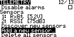
FrSKY sensors are added from the telemetry screen.
Telemetry units and decimal precision are automatically configured for FrSKY sensors. Their minimum and maximum values are also automatically tracked.
Individual telemetry may be reset using a special function. All telemetry may be reset using a special function or from the main view and telemetry view context menus.
Settings such as sensor name, auto offset, filtering, persistent storage at power off, turning logging on and off are configurable. Note that for logging to work logs have to be configured on the special functions screen as well (more…).
Duplicating sensors are allowed and each copy may have different configurations. For example their units may be changed so that one sensor may have its units in meters while another copy of it has it in feet. Another example is to configure them so that one sensor gives the altitude above sea level while the other gives the altitude relative to ground.
Multiple identical physical sensors are supported as long as they have a unique instance number. For example an FrSKY current sensor by default usually has an instance number of 3. An FrSKY channel changer may be used so that a second current sensor has an instance number of 13 (more…). These two current sensors may now be used together.
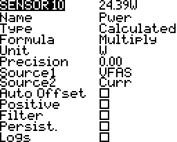
Calculated sensors use one or more sensor to calculate a value. For example a current sensor may be used to calculate the mAH used. Another example is adding the voltages from two different voltage sensors. There two examples can be combined to calculate power (voltage x current).
Screen Layout
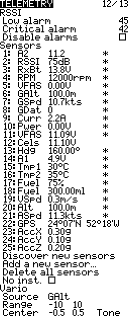
RSSI
Received Signal Strength Indicator in dB (decibels)
RSSI is the relative received signal strength in a wireless environment, in arbitrary units. RSSI is an indication of the power level being received by the receive radio after the antenna and possible cable loss. Therefore, the higher the RSSI number, the stronger the signal. More…
– Wikipedia
- Decibels are logarithmic. More…
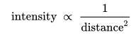
- Radio waves follow the inverse square law for power density. More…
The power density is proportional to 1/distance squared.
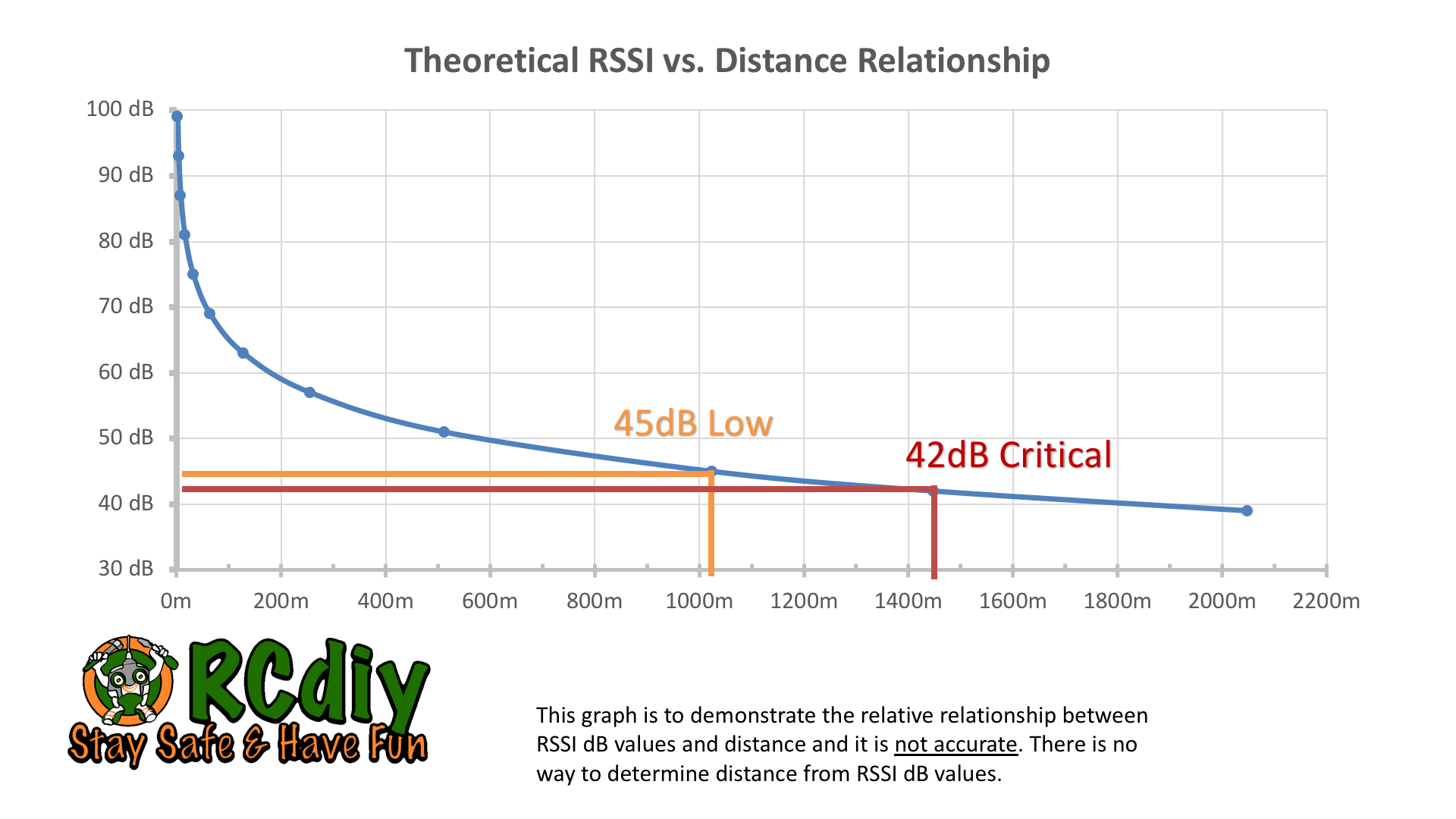
- There is no way to determine distance from the RSSI value. There is however a relationship between RSSI value and relative distance with interference and reception conditions remaining unchanged. More…
- For every 3dB change the power density changes by 2x. (Decibel scale power ratio)
- For every 6dB change the power density changes by 4x.
For every 2x change in distance the power density changes by 4x. (Inverse square law)
So 6dB change occurs with 2x distance change. - For every 6 dB loss in RSSI there is a doubling of the distance.
- For every 3db loss in RSSI there is a 1.4x change in distance.
- For example if a signal low warning is heard at about 1 km then it is likely that the RF signal critical warning will be heard at 1.4 km and possible control loss will occur by the time 2 km is reached.
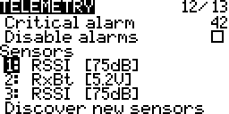
Low & Critical Alarms
When the RSSI value goes below these values (45 and 42) an audio alert is heard. It is recommended that these values be kept unchanged.
If an SD Card with the appropriate sound pack is present then the alerts are announced else beeps will be heard. More…
- “RF signal low”
- “RF signal critical”
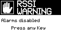
Disable alarms
The RSSI low and critical alerts will not occur.
When loading the model a warning will be displayed.
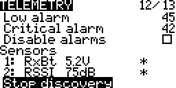
Sensors
A list of sensors connected to the system. Sensors may be selected and edited.
Columns
- Line Number:
 A number assigned similar to a numbered list. This helps distinguish duplicate sensors.
 - Name:
 The name as it appears is source lists.
 - Value:
 The sensor value with units.
- Telemetry Received:
 Values recently received. May blink if the update is slow. Will disappear if no updates.
 - Sensor Lost:
 Connection to the sensor has been lost.
- Telemetry Received:
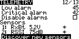
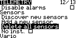
Discover New Sensors
Turn on discovering new sensors.
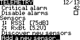
Add A New Sensor
Add a new custom or calculated sensor.
Delete All Sensors
Delete all the sensor in the sensor list.
No / Ignore Instances
To be used with non FrSKY sensors which may have faulty software that fills up all the sensor slots. In Companion this is called disable multi sensor handling. This is rarely needed.
Vario
The sensor being used for the variometer.
Range
The climb and sink range within which to change the variometer tones.
Center
The range within which to ignore climb and sink.
Tone/Silent
Play a tone or stay silent within centre range.
Sensor & Telemetry Alerts
Sensor Lost
When the connection to the sensor is lost for about ten seconds an audio alert is heard. If an SD Card with the appropriate sound pack is present then the alerts are announced else beeps will be heard. More…
- “Sensor lost”
Telemetry Lost
When the connection to the receiver is lost or recovered an audio alert is heard. If an SD Card with the appropriate sound pack is present then the alerts are announced else beeps will be heard. More…
- “Telemetry lost”
- “Telemetry recovered”
Editing
General editing instructions are covered on the Screen Navigation page under editing.
Discover New Sensors
- Select Discover new sensors
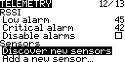
- Press ENTER
- Wait for sensors to appear
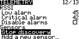
- Select Stop discovery
Press ENTER
Add A Custom Or Calculated Sensor
- Select Add a new sensor
- Press ENTER
- Scroll down to Type
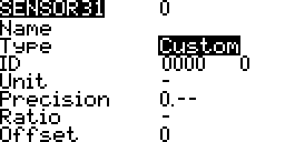
- Press ENTER

Delete All Sensors
- Select Delete all sensors
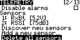
- Long Press ENTER
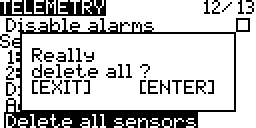
- Press ENTER
Edit
- Long Press ENTER
Select ENTER
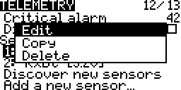
- Press ENTER
Copy
- Long Press ENTER
Select Copy
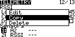
- Press ENTER
Delete
- Long Press ENTER
Select Delete
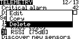
- Press ENTER
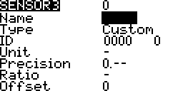
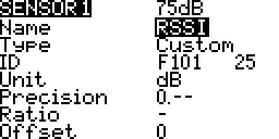
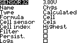
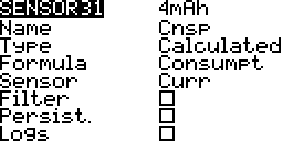
Settings
Sensors
Name
The name as it appears is source lists.
Each sensor has two auto generated sensors for their minimum and maximum values. They share the same name with a negative and positive symbol added to the end.
- Minimum:
 An auto generated sensor minimum value variable that appears in the source lists.
 - Maximum:
 An auto generated sensor maximum value variable that appears in the source lists.
Type
The settings available and their behaviour change depending on the type of sensor.
Custom
Sensor that are automatically added by discovery are custom sensors. Their configurations are automatically added and do not usually need to be edited.

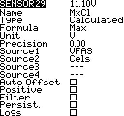
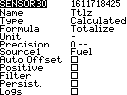
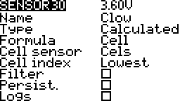
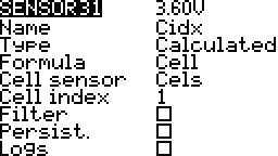
Calculated
Calculated sensors use one or more sensors to provide telemetry based on the sensor values and a calculations. There is more information in the calculated sensors section below.
Custom Sensor ID
Consists of two parts.
- Hardware ID Number – This unique to sensor type. For example 0210. These do not need to be unique. More than one sensor of the same type may be connected. For example two voltage sensors.
- Hardware Instance Number – This is assigned in the sensor hardware. For example the FrSKY current sensor has a voltage sensor with an instance number of 3. For FrSKY sensors this may be changed using an FrSKY servo channel changed (more…). When using two sensors of the same type this instance number must be different on each sensor.
Calculated Sensor Formula
There are a number of formulas that are available. These are covered in the calculated sensors section below.
Units
The units of the sensor values. There are over twenty units available. Some examples are meters (m), kilometers per hour (km/h), feet (ft), and fluid ounces (fOz). These units are important for display and audio announcements of sensor values.
Precision
The number of decimal places to display. The value is not rounded; Digits are truncated.
- 0.– ⇒ 11V
- 0.0 ⇒ 11.1V
- 0.00 ⇒ 11.18V
Ratio
The multiplier to use to get the correct reading; Usually in volts. Using a multimeter measure the voltage. If the multimeter voltage and sensor voltage do no match adjust the ratio until they match. More…
Auto Offset
Used to calculate values relative to an initial value. The initial value is the value at telemetry reset or when the sensor first reports a value. For example calculating altitude with respect to ground instead of with respect to sea level. More…
Positive
Only use positive values. If the values are negative return zero.
Filter
Used to smooth values that change a lot. Values are averaged over the sensor’s last few reported values.
Persistant
Values are retained between model changes and power cycles. The next time the model is loaded the last recorded sensor value is retained. For example the last mAh is added to the present mAh calculations to get a total over multiple flights.
Logs
The sensors values will be added to the logs if logs have been setup and enabled on the special functions screen. More…
No / Ignore Instances
To be used with non FrSKY sensors which may have faulty software that fills up all the sensor slots. In Companion this is called disable multi sensor handling. This is rarely needed.
Vario
Select the Variometer source and settings. A variometer provides a glider’s sink and climb rates using an altitude sensor. As the aircraft sinks and climbs a tone is heard and its pitch changes.
Range
The range within which to change the variometer tones. Sink and climb rate limits when the tone pitch change stops. Beyond these limits the tone stays the same. The units are that same units as the variometer source; meters per second or feet per second.
Center
The range within which to ignore climb and sink. When the climb and sink rates go outside these settings the tone changes pitch. The units are that same units as the variometer source; meters per second or feet per second.
Calculated Sensors
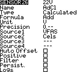
Add
Add telemetry source values. Up to 4 sources. For example add individual cell voltages to get the total voltage.
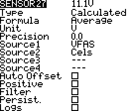
Average
Average telemetry source values. Up to 4 sources. For example the average voltage of individual cells.
Minimum
Minimum value from source values. Up to 4 sources. For example the minimum voltage of individual cells.

Maximum
Maximum value from source values. Up to 4 sources. For example the maximum voltage of individual cells.
Multiply
Multiply two source values. For example current multiplied by voltage to give power in watts.
Totalize
Adds the sensor value to a cumulative total. This was developed for a fuel sensor that did not get released. More…
Cell
This is for the FrSKY lipo sensor that connects to the lipo balance connector.
Lowest
Lowest cell voltage.
Index
Volage of a particular cell.
Highest
Highest cell voltage.
Delta
The difference in voltages between the highest and lowest cell voltages.

Consumption mAh
The mAh used based on the current sensor values.
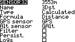
3D Distance
The distance between the pilot and the aircraft. If the altitude source is specified then the distance is from the pilot to the aircraft in the air. If the altitude source is not specified then the distance is from the pilot to the ground location below the aircraft. More…
Telemetry Reset
Telemetry initial reference values and minimum and maximum values get reset.
- Calculated sensors such as height above ground calculate their values with respect to the value at reset.
- Consumption sensors such as mAh consumed get reset to zero.
- The GPS pilot latitude and pilot longitude get reset to the current position.
- Minimum and maximum values get set to the sensor’s current value.
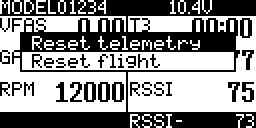
Main View
- From the main view screen

- Long Press ENTER
Scroll to Reset
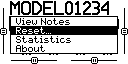
- Press Enter
Select Reset telemetry
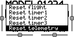
- Press ENTER
Telemetry View
- From the telemetry view screen

- Long Press ENTER
Select Reset telemetry
- Press ENTER
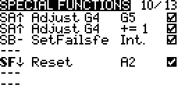
Special Functions
- Press ENTER on the switch field
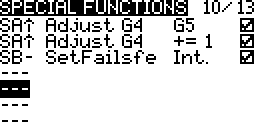
- Move a switch to set the switch that will be used to do the reset
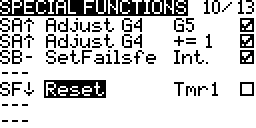
- Select Reset as the function
Select Telm to reset all telemetry sensors

Select the individual sensor name to reset only that sensor
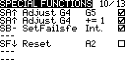
- Check the enable box at the end
Telemetry Switches
Telemetry switches are active when telemetry data is being produced. These switches are used on model menu special functions and logical switches screens as an activation switch.
Examples
Special Functions
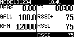
A special function could be configured so that when the GPS altitude sensor is sending telemetry have its value announced every fifteen seconds. When there is no telemetry yet or telemetry has been lost do not announce its altitude.
Switch inactive: GAlt telemetry not being received, no announcements.
Switch active: GAlt telemetry being received, announcements every 15 seconds.
Logical Switches
A logical switch could be configured so that it is true only when the throttle is not idle and telemetry is being received. This logical switch could then be used in a special function to announce telemetry values. This could be one way to only have announcements while the aircraft if flying and not on the ground.
Switch inactive: Throttle is idle or telemetry is not being received.
Switch active: Throttle is not idle and telemetry is being received.
Examples & Guides
Telemetry
- Altitude On Model Screen Top Bar
- Display Sensor Values
- Display Telemetry Screen
- Enabling Sensor Telemetry Logs
- Rename A Sensor
- Reset Telemetry & Relative Readings
- Telemetry Display On An iPad or iPhone
Sensors
A2 Sensor
- Lipo voltage being measured 3S-5S using the FBVS-01 voltage divider.
- Sensor voltage divider ratio is 6:1 @ the 3S setting.
- OpenTX sensor ratio will be 6 x 3.3 = 19.8
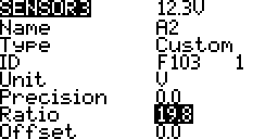
- Using a multimeter measure the voltage.
If the multimeter voltage and sensor voltage do no match adjust the ratio until they match.