
OpenTX
Contents
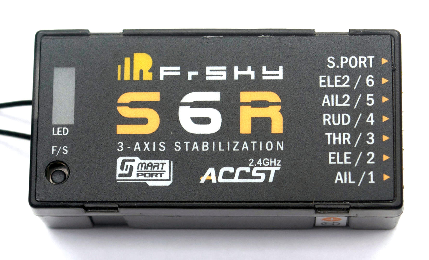
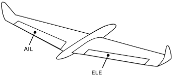
Receiver
Description
- Receiver with Gyro & Accelerometer
- Stabilize, Auto Level, Knife Edge, Hover and Urgent modes
Stabilize Mode
- Orientation changes due to wind are reduced.
- The receiver compensates for the changes using the ailerons, elevator and rudder.
- The compensation amount can be adjusted in flight by the pilot using a knob or may be set to a fixed value.
- The pilot uses the throttle, ailerons, elevator and rudder to control and fly the aircraft.
Auto Level Mode
- The aircraft is rolled and pitched in proportion to aileron and elevator stick position. Holding the aileron stick steady to bank the aircraft keeps the aircraft in a steady bank. Release the stick to neutral brings the aircraft back to level flight.
- The receiver controls the ailerons and elevator to orient the aircraft in proportion to stick position.
- The receiver controls the rudder the same way it does in stabilization mode.
- The pilot uses the throttle, ailerons, elevator and rudder to control the aircraft.
Note: Level, auto level, self level and SLM are all terms used for the same mode.
Hover Mode
- The aircraft is pitched nose up and kept hovering like a helicopter.
- The receiver controls the elevator and the rudder.
- The receiver controls the aileron the same way it does in stabilization mode.
- The pilot uses the throttle to control the altitude and the ailerons to control the rotation about the vertical axis.
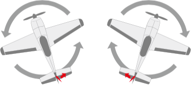
Knife Edge Mode
- The aircraft is rolled on it’s side, with one wing pointing up and the other pointing down, and kept flying this way.
- The receiver controls the aileron and rudder.
- The receiver controls the elevator the same way it does in stabilization mode.
- The pilot uses the throttle and rudder to control the altitude and the elevator to control the direction.
Urgent Mode
- Regardless of orientation recovers the aircraft to level flight.
- This is also known as panic, recover, oops and “Oh shit!” mode.
Setup
This documentation is based on using OpenTX and its Lua scripts run on the Taranis series of transmitters.
Links have been provided to documentation for ErSky9x/Er9x under the relevant sections.
Tips & Notes
- SxR Manual – Please read the latest manual on the FrSKY website. The manual received with the receiver may be out of date. This web page is not a replacement for the S6R, or S8R manual.
- Experience – This receiver and instructions are to be used after some experience has been gained setting up models, using a FrSKY transmitter with receivers, OpenTX and flying.
- Follow Each Step – The first time the S6R or S8R receiver is set up follow the steps exactly as shown here. Don’t skip any of the steps or change them.
- Do Not Install The Receiver – Do not install the receiver in a model until all the steps have been done at least once on the bench. Have 3 to 4 servos with arms attached available for testing.
- Spare Receiver – The first few times the S6R/S8R receiver is set up have a spare one on hand as a backup. These receivers can be configured to operate as simple X6R or X8R receivers by turning off the gyro features; These receivers are unlikely to go to waste.
- OpenTX Lua Scripts – The Lua scripts used are downloaded from OpenTX using Companion; Not from the FrSKY website. One advantage of using the Lua scripts is that at the field one will will always have everything needed to configure the receiver.
- OpenTX Version – OpenTX 2.2.1 or later is required for these Lua scripts. The Companion “lua” firmware build option is not required.
- STK Tool – The STK tool is not used in this guide. If the STK Tool is used make sure the servos and battery are disconnected from the receiver.
- Free Link – The FrSKY bluetooth mobile app is not used in this guide.
LED Status Lights
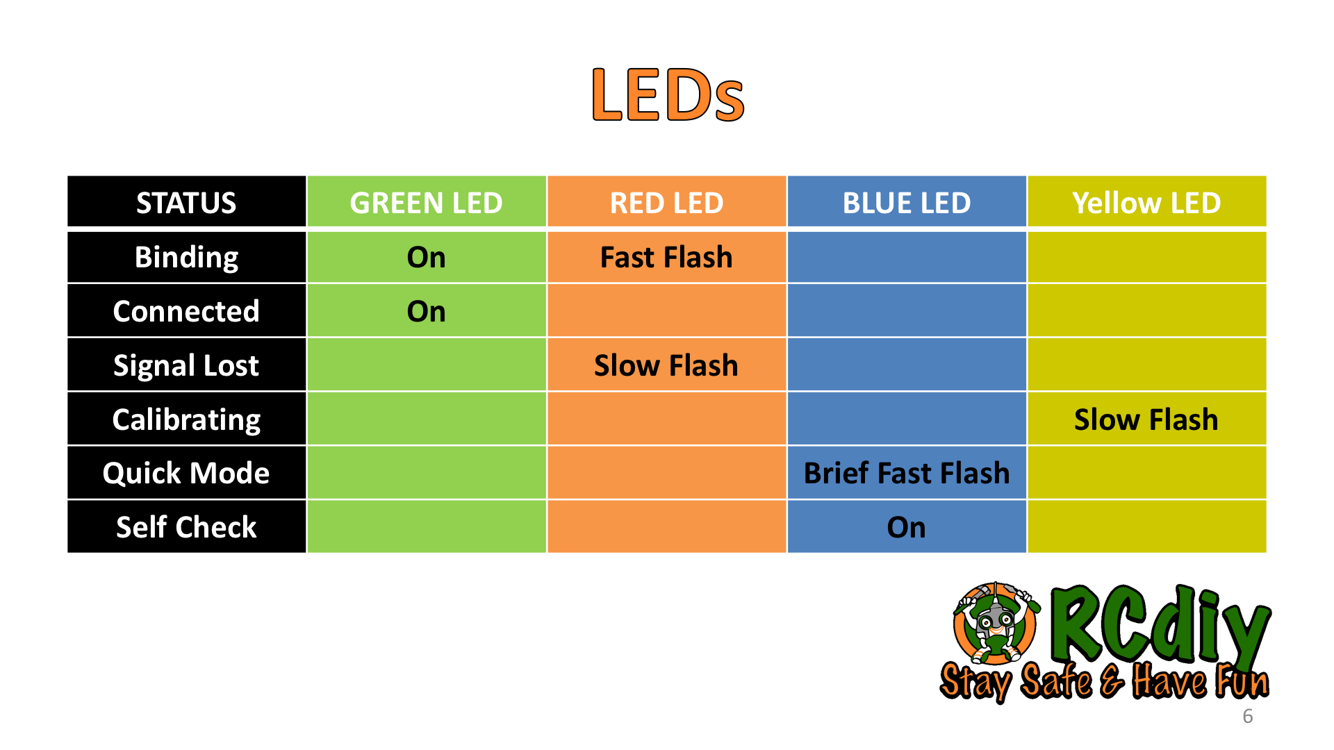
There are two additional LEDs on these receivers.
- Yellow LED – Slow flashes during calibration when the receiver is being written to. When slow flashing keep the receiver stationary.
- Blue LED
- Quick Mode – When the receiver is powered on quick and brief flashing of the blue LED indicates that the receiver is operating in Quick mode.
Note: Depending of firmware version the blue led may or may not come on with power on. Use the Lua script to determine if Quick Mode is enables. - Self Check – When the receiver self check is initiated the blue LED comes on and stays on till the control surfaces stop moving. As soon as the blue LED turns off move the sticks to their limits. More on this below.
- Quick Mode – When the receiver is powered on quick and brief flashing of the blue LED indicates that the receiver is operating in Quick mode.
Program The Transmitter
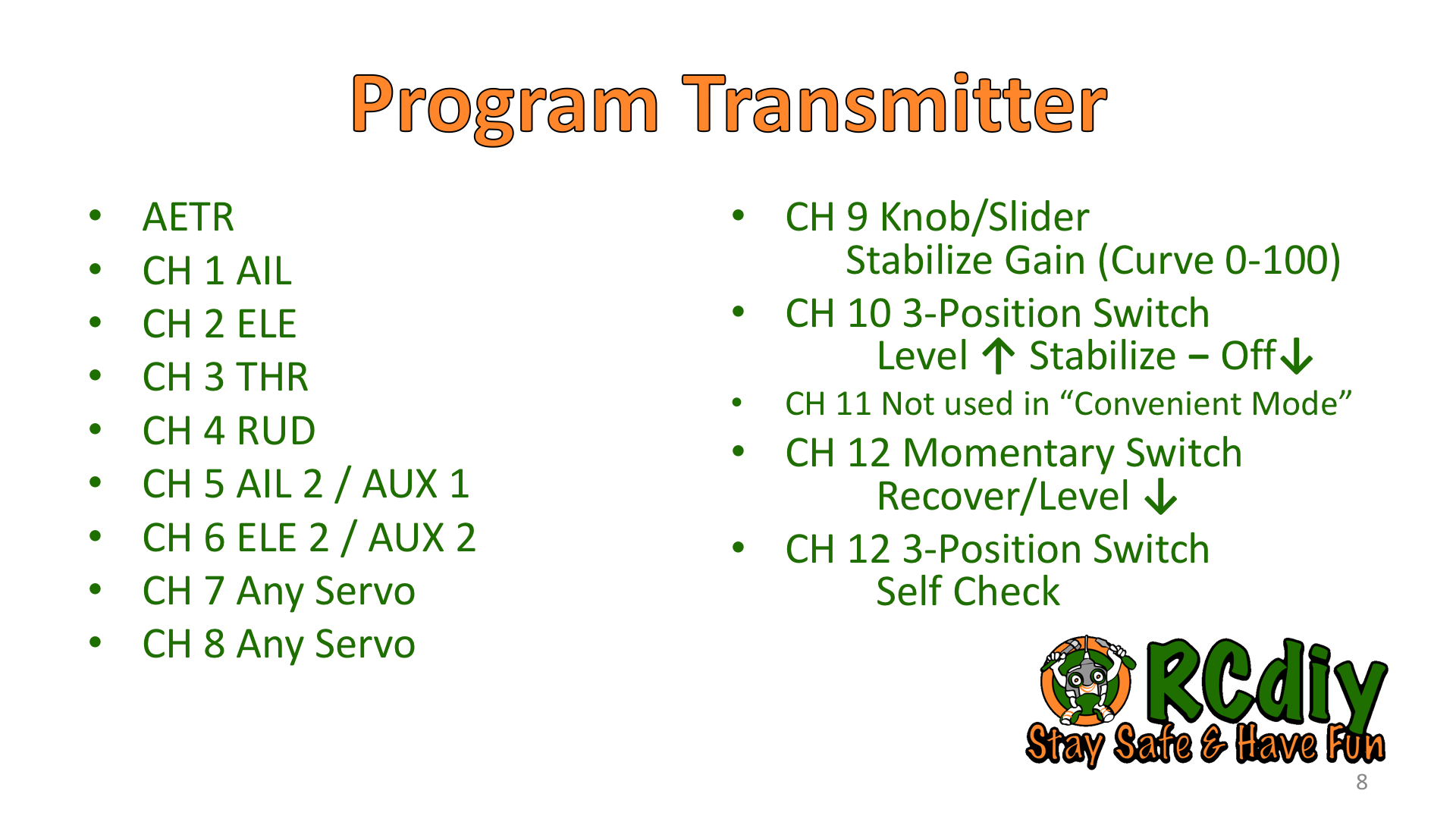
- Sample model file – SxR.otx (Taranis X7)
- Sound files – SxRannouncements.zip
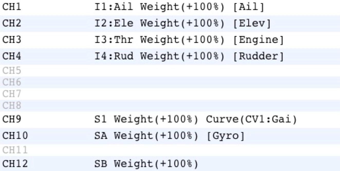
- Channels 1 through 4 – use direct input to output mixer mapping. Do not add any mixes for flying wings or V tails. The receiver does the mixes for these when configured.
- Channel 5 – Can be ignored if using a Y cable for the Ailerons on channel 1 (Aileron).
- Channel 6 – Can be ignored if using a single servo on channel 2 (Elevator).
Note: Channels 5 & 6 are part of the self check even if they are set to auxiliary.
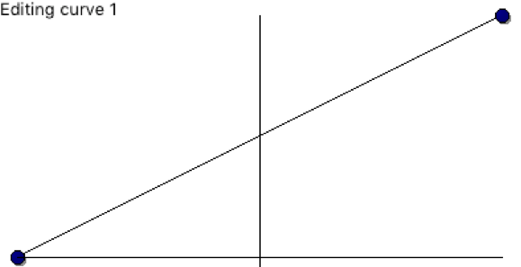
If these channels are used for landing gear disconnect the servo wires during the self check. - Channel 9 – Place on a knob so that it can be adjusted in flight.
By default when the knob is centered the gain gets set to zero and no stabilization will occur in stabilize mode. Make sure the gain is not zero for stabilization to work.
Place this knob on a curve so that when it is all the way counter clockwise the gain is zero and when it is all the way clockwise the gain is at maximum. When it is centered the gain is at half.
To learn about using curves watch the Painless360 video Using OpenTX Companion and Curves.
Y = 0 when X = -100
Y = 100 when X = 100


- Channel 10 – 3 position switch.
- Channel 11 – 3 position switch. Can be ignored if using Quick Mode.
- Channel 12 – First gets put on a 3 position switch. This is so that the self check can be initiated using it.
After the self check is done and before the first flight remember to put channel 12 on a momentary switch. This is so that urgent mode may be used and to prevent self check from initiating during a flight. You may also choose to not use any switches.
Bind Receiver to Transmitter
- Model SETUP screen
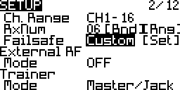
- Mode: D16
- Channel Range: 1 to 16
Make sure the channel range is 1 to 16 because the default is 1 to 8. - Set the failsafe: Custom
- CH3 (THR) – Minimum, -100%
- CH1 CH2 CH4 (AIL, ELE, RUD) – Left or right turn
- CH 9 (GAIN) – Non zero value
- CH10 (Level/Stabilize/Off) – Minimum, -100% (Level)
- CH12 (Recover) – Minimum, -100% (Recover not activated)
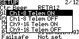
- Bind Option: Ch1-8 Telem ON
To learn more about the bind options read the D16 Bind Options documentation. - Receiver Number: Pick any receiver number not used by another model on the transmitter.
- Bind Problems: If there is trouble binding change the number and try again. An update to the most recent transmitter and receiver firmware may be needed.
Select & Flash Firmware
Flash the receiver with the latest firmware that has the Quick mode. Download S6R, S8R. Once flashed label the receiver with the firmware number.
There is no way to determine which firmware is on the receiver. Flashing the receiver to the most recent will ensure that the version on it is known and that following this guide will hopefully lead to success.
To flash the receiver follow the S.Port Firmware Flashing guide.
The firmware may default to quick mode which is indicated by the blue LED which flashes quickly and briefly on powering on the receiver.
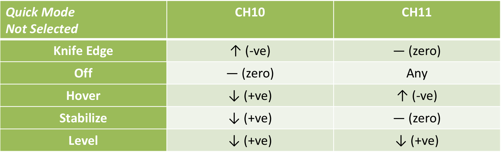
Switch Positions For Flight Modes
Quick Mode
Quick, Simple and Convenient are all different names for the same mode.
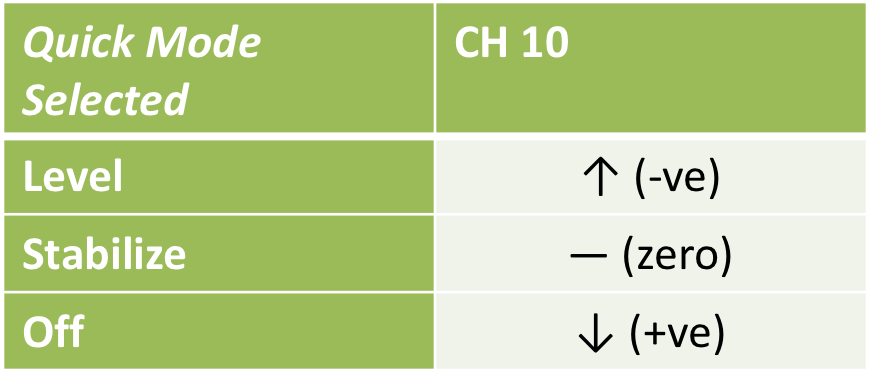
In this mode a single channel, channel 10, switches between Auto Level, Stabilize and Gyro Off flight modes.
- Channel 10
- Auto Level, Stabilize and Gyro Off
- Channel 12 ↑
- Urgent mode
Non Quick Mode (Advanced)
When the firmware is in non quick mode two channels, channels 10 and 11, are used to switch between Auto Level, Stabilize, Knife Edge, Hover and Gyro Off flight modes.
- Channel 10 & 11
- Knife Edge, Off, Hover, Stabilize, Auto Level and Gyro Off
- Channel 12 ↑
- Urgent mode

Calibrate Receiver
The receiver calibration only needs to be done once when it is first used.
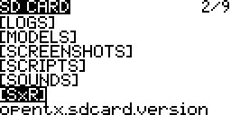
The Lua script is obtained from OpenTX by following the Downloading The SD Card Contents guide.
ErSky9x – Has a dedicated menu for calibrating the SxR receivers. S6R/S8R – Instructions
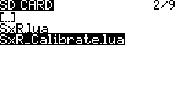
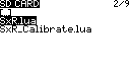
This script is in the SxR folder and is called SxR_Calibrate.lua.
- Transmitter Sticks – Throttle down with rest centered.
- Power – Turn on the transmitter and then the receiver.
- Connect – Check that they are connected. The green LED will be on.
- Lua Script – Using the SD Card screen Launch the Lua script from the transmitter.


- Follow the instructions on the screen.
- The instructions will guide the placement of the receiver on each of its 6 sides.
- A small block of wood or a table edge to rest the the Rx in a couple of the orientations will be needed.
- The receiver needs to be kept still while the yellow LED blinks for about 5 seconds.
Configure Receiver
The Lua script is obtained from OpenTX by following the Downloading The SD Card Contents guide.
ErSky9x – Has a dedicated menu for configuring the SxR receivers. S6R/S8R – Instructions
This script is in the SxR folder and is called SxR.lua.
- Transmitter Sticks – Throttle down with rest centered.
- Power – Turn on the transmitter and then the receiver.
- Connect – Check that they are connected. The green LED will be on.
- Lua Script – Using the SD Card screen Launch the Lua script from the transmitter.

Wing Type & Receiver Mounting Orientation
- On page one of the script set the wing type.
- Normal
Delta (Flying Wing)
V-tail
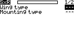
- Normal
- Set the mounting type (orientation):
- Horzontal, Pins towards the tail, Label facing the sky (Default)
Horzontal reverse, Pins towards the tail, Label facing the ground
Vertical, Pins towards the tail, Label facing the left wing
Vertical reverse, Pins towards the tail, Label facing the right wing
- Horzontal, Pins towards the tail, Label facing the sky (Default)
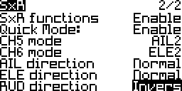
Enable Quick Mode, CH 5 & 6 Modes, Gain & Offset Angles
- On page two of the script set:
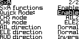


- SxR functions – Enable
- Quick Mode – Enable
Note: With some receivers Quick Mode’s settings, Enable/Disable, is not shown. If you have this problem then use this Lua script file.
X7 series SxR-X7.lua
X9 series SxR-X9.lua
Horus series SxR-Horus.lua - CH5 & 6 mode – AUX or AIL2/ELE2
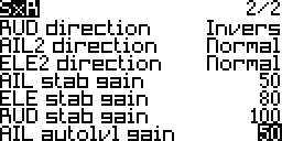
- Leave the direction, gain and offset values at their defaults.
- The gain settings are used to adjust the surface deflection amounts. When set too low the desired orientation may not be reached or may take too long to be reached. When set too high the aircraft may oscillate back and forth. Example video of too much elevator gain.
- The offset angles are used to trim the aircraft in their respective modes. This is done while on the ground; Not in flight.
Mounting The Receiver
When mounting the receiver orient it as closely aligned/parallel as possible with the nose-to-tail axis and the left-to-right-wing axis. Place the receiver as close as possible to the centre of gravity (CG).
Aircraft Servos & Channels
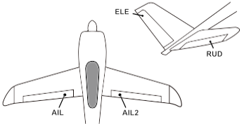
Connect the aircraft servos to the pins labeled on the receiver as shown in the diagrams below.
Auxiliary Mode for Pins/Channels 5 and 6 enable them to be used for functions other than a second aileron and elevator servo. However even when in auxiliary mode these pins take part in the self check procedure. If these pins are connected to landing gear there will be an undesired motion. During self check temporarily disconnect the landing gear servo wires if connected pins 5 and 6.
Wing Types & Servo Connections
Conventional Wing
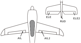
- ELE2 may be ignored if only a single servo is used for the elevators.
- AIL2 may be ignored if a Y cable is being used to connect both aileron servos.
Delta Wing
Note: The RUD pins on channel 4 output the rudder control from the transmitter plus stabilization from the receiver in auto level and stabilize modes.
V-Tail
Aircraft Servo Throws
Connect the servo arms so that there is equal travel on either side of center for the control surfaces.
Transmitter Servo Limits
Configure the servo travel limits on the transmitter’s OUTPUTS screen. This is important to prevent servo binding/jamming which could result in damage. More…

Self Check With Calibration
Explanation
The self check with calibration is process that determines
- what level is,
- the servo throw limits to prevent jamming,
- and the transmitter sticks’ neutral positions.
This is usually done once or twice per installed model and is repeated if
- the stick centre trim positions have changed
- the throws are too large or small
- the aircraft does not fly level in auto level mode
- the receiver position in the aircraft has changed
Preparation

- Propeller – Remove the propeller. Put it back on when done.
- Level – Orient the aircraft with the wings level.
- Nose Up – Orient the aircraft with the nose slightly elevated.
- Stationary – The model must not move. If it is windy hold the model stationary.
- Throttle Down – The throttle stick is kept held down.
- Switches – The channel 10 and 11 switches may be in any position.
- High Rates – If rates have been set up then switch to high rates.
- Servos – Connect the servos. If landing gear uses pins 5 and 6 disconnect them. Remember to reconnect them after the self check.
Execution
- Transmitter Sticks – Throttle down with rest centered.
- Power – Turn on the transmitter and then the receiver.
- Power On Blue LED – If the blue LED flashes wait for it to stop. This indicates that quick mode is active.
- Start Self Check
- FS Button – Press the F S button to enter the self check process.
Or - Channel 12 On A 3 Position Switch – If a 3 position switch is on channel 12 move it in and out of the center position 3 times within 3 seconds.
- FS Button – Press the F S button to enter the self check process.
- Self Check Blue LED – The blue LED turns on and the servos move. Wait till the blue LED turns off and the servos stop moving.
- Set Limits
- Immediately move the elevator, aileron and rudder sticks to their limits.
It is not necessary to move the throttle. - If a switch, knob or slider is on channels 5 or 6 move it to its limits as well.
- Immediately move the elevator, aileron and rudder sticks to their limits.
- End Self Check – Power off the receiver.
Verification
- Transmitter Sticks – Throttle stick down with rest centered.
- Power Cycle – Turn off the receiver and then turn it on again.
- Auto Level Mode
- In quick mode this is done by moving the channel 10 switch up and away from the pilot.
- Check Servo Movement
- Raise and lower the tail and then do the same to one of the wings.
- The elevator and ailerons will move.
- If they don’t move or don’t move enough repeat the self check.
- Move the sticks to their limits
- The elevator and ailerons will move to their limits.
- If they don’t move or don’t move enough repeat the self check.
- Move the switch, knob or slider on channels 5 and 6.
- The auxiliary functions should work.
- If the don’t work as expected repeat the self check.
- Raise and lower the tail and then do the same to one of the wings.
Servo Directions
Receiver/Gyro Directions
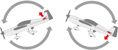
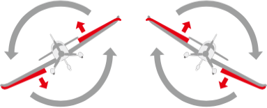
- Auto Level Mode – Place the receiver in auto level mode.
- In quick mode this is done by moving the channel 10 switch up and away from the pilot.
- Check Servo Movement – Visualize a hand opposing the action.
- Raise the tail up and the elevator should also also go up in proportion to how much the tail was raised.
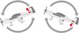
- Raise the left or right wing up and the same aileron should also also go up in proportion to how much the wing was raised.
- Jerk the tail left. The rudder should go left.
- Raise the tail up and the elevator should also also go up in proportion to how much the tail was raised.
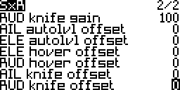
- Correct The Direction Using The Lua Script
- To correct the directions launch the SxR.lua script and go to page two.
- Scroll down to the relevant control surface and press enter to change its direction.

- Repeat the servo direction test.
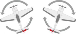
Transmitter Directions
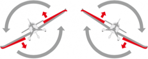
- Position Transmitter Over Aircraft From Behind – To test the transmitter servo directions stand behind the aircraft and hold the transmitter over it.
- High Five – Visualize a hand opposing the action.
- Move the elevator stick down and the elevator on the model should move up to meet it.
- Move the aileron stick left and the left aileron should move up to meet it.
- Move the aileron stick right and the right aileron should move up meet it.
- Move the rudder stick left and the rudder moves left to meet it.
- This is like doing a high five where the two hands and their fingers meet up.
- Correct The Direction On The OUTPUTS Screen
- To correct the directions go to the OUTPUTS screen and edit channel directions.
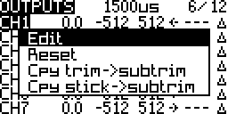
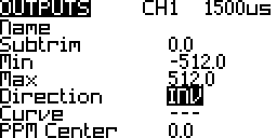
- To correct the directions go to the OUTPUTS screen and edit channel directions.
First Flight
- Calm Day – Pick a calm day if possible.
- Channel 12 Momentary Switch/Disable – If Channel 12 was on a 3 position switch change it to a 2 position momentary switch or remove that mix line to disable it. This prevents self check being initiated by mistake during flight.
- Practice Flight Modes – Practice placing the receiver gyro in the different modes; off, stabilize and auto level.
- Gain Knob – Set the gain knob at 50% which is the center position of the knob.
- Servo Directions Test – Check the servo directions again before take off.
- Test Failsafe – Do a failsafe test.
- Range Test – Do a range test.
- Hi/Low Rates – If configured is a personal preference or follow the aircraft documentation (if any).
- Gyro Off (↓) – In quick mode this is done by moving the channel 10 switch towards the pilot.
- Take Off – Take off with the Gyro turned off.
- Altitude – Gain some altitude before performing the tests for each flight mode.
In Flight Tests
- Gyro Off (↓) – Trim for level flight using the transmitter trims.
- Stabilize Mode (-) – In quick mode this is done by moving the channel 10 switch to the center.
- Roll, Pitch, Yaw Problems – If any of these problems exist switch to off mode and land immediately. Correct the problem and repeat the in flight tests.
- Roll ↔ Aileron – If the model goes into a roll the aileron servo direction may be reversed.
- Pitch ↔ Elevator – If the model goes into a dive or climb the elevator servo direction may be reversed.
- Yaw ↔ Rudder – If the model goes into a turn the rudder servo direction may be reversed.
- Test different gain settings – If the model oscillates back and forth the gain may be too high. Turn it down.
- Trim For Level Flight – Trimming should not be required.
- Roll, Pitch, Yaw Problems – If any of these problems exist switch to off mode and land immediately. Correct the problem and repeat the in flight tests.
- Land
Second Flight
- Redo Self Check
Once the model has been trimmed in flight the neutral position for the Level Mode has changed. The neutral positions correspond to level flight.
Example: To fly level left aileron trim was applied. The aileron signal is no longer at the neutral position for level mode. Now when level mode is activated the plane is level to start but the receivers receives left aileron which it now interprets as bank left. The plane will roll left. - Take Off – Take off with the Gyro turned off or in stabilize mode.
- Altitude – Gain some altitude before performing the tests for each flight mode.
In Flight Tests
- Auto Level Mode (↑) – In quick mode this is done by moving the channel 10 switch away from the pilot.
- Do not test auto level mode if stabilization mode does not work.
- Trim For Level Flight – There are a number of ways to trim for level flight.
- In-flight use the transmitter trims.
- Land and use the SxR.lua script to change the auto level angles. More on this below under After First Flight.
- Land and redo the self check.
- Bank and pitch the model and then center the stick.
- The model should hold a bank or pitch and then return to level flight.
- If oscillating of the aircraft wings or tail occurs then the aileron or elevator gain have been set too high. Use the Lua script to change the auto level gain. Example video of too much elevator gain.
- Urgent Mode (↓) – In quick mode this is done by moving the channel 12 momentary switch towards the pilot.
- Do not test urgent mode if auto level mode does not work.
Urgent mode is a form of quick acting auto level mode so if auto level does not work neither will urgent mode. - Bank the model to one side a bit and then test recover mode.
- Pitch the model up and then test recover mode.
- Fly inverted and then test recover mode.
- Do not test urgent mode if auto level mode does not work.
After Flight Tests
- Channel 9
- Fixed Value – Consider if channel 9 is to be changed to a fixed value instead of using the knob. This way remembering and setting the knob’s position when flying is unnecessary.
- Narrower Range – Consider if channel 9 knob’s curve is to be changed to operate in a range above 0 and less than 100. This way even if you forget to set the knob it will not be too high or too low.
- Do one of the following at a time. If the servo push rod trim is done then do another test flight before either redoing the servo push rod trim or picking one of the other adjustment methods. The same goes for the other adjustment methods; use only one method at a time between flights.
- Servo Push Rod Trim – Adjust the aircraft servo push rods so that the surfaces stay at their trim position but the transmitter trims may return to their center positions.
- Self Check
- Redoing the the self check with the model at a different level orientation compared to orientation used during the previous self check may help.
- Pitch – If the aircraft pitched down when entering auto level mode then redo the self check with the nose angled further up. Do the opposite if the aircraft pitched up.
- Roll – If the aircraft rolled when entering auto level mode then redo the self check with the wings level.
- Auto Level Offset Angle (Rarely Required)
- This is rarely required. Usually redoing self check is enough to fix problems with level mode.
- If the plane was not flying level adjusting the Aileron and elevator auto level offset may help. To do this use the SxR.lua script.
- Experiment with different settings.
- Failsafe – Depending on how the failsafe was set up it may need to be redone.
Example: The aileron failsafe may be set for level flight at 1500μs but after the plane is trimmed it might actually be at 1600μs.- If the servo rods were adjusted and trims reset to zero then the failsafe would stay at 1500μs.
- If the trims were transferred to sub-trims then the aileron failsafe would be changed to 1600μs.
- Repeat – The in flight tests may have to be repeated a couple more times.
Help & Support
- Aloft Hobbies Forum
- Flite Test Forum
- RC Groups (Public Forum Thread)
When asking for help include the following:
- Receiver type S6R/S8R
- Firmware version number
- Problem/question
- Link to instructions followed (this page) if relevant
Feedback
- RC Groups (Personal Blog Thread)
Credits
- FrSKY SxR Manuals S6R, S8R
- FrSky S6R and S8R Receiver, Setup Info For Beginners And Users By TooManyToys
- FrSky S6R 6CH Receiver With 3-Axis Stabilization With Smart Port Telemetry
- RCdiy S6R Web Post Feedback By RCdiy