
Contents
Screen Layout
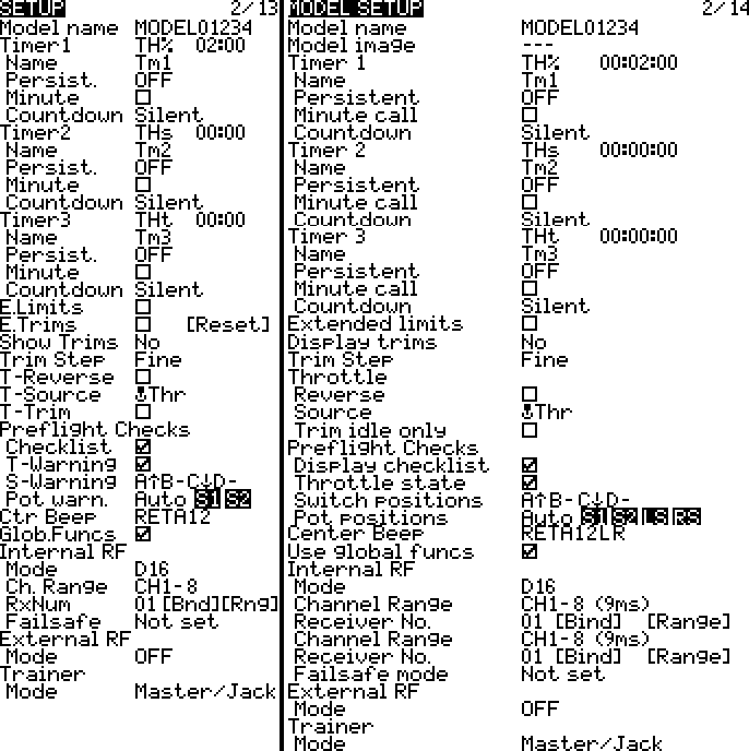
Taranis Q X7 series on the left & Taranis X9 series on the right
Editing
General editing instructions are covered on the Screen Navigation page under editing.
Settings
Model Name
Name displayed on the main view and model menu select screens.
Model Image
Image displayed on the Main View screen.
64 x 32 pixels, 16 bit, grayscale, .bmp file, IMAGES folder of the SD card
Not available on the Taranis Q X7 series of transmitter.
Timers
Three timers, that can count either up or down.
- ON – Always running.
- Tht – Throttle up triggered, starts the first time the throttle is not all the way down
- THs – Throttle not idle triggered, starts and runs when the throttle stick isn’t all the way down.
- TH% – Throttle percentage triggered, runs as a percentage of the throttle stick position.
Throttle all the way down is 0%, timer stopped.
Throttle at 50%, timer runs at 50% speed (not real time).
Throttle all the way up is 100%, timmers runs in real time. - Note: The throttle trigger source can be changed from the throttle stick to a channel or a slider. More on this is the throttle settings below.
- Value – MM:SS, minutes and seconds.
Set to 00:00 to count up.
Set to non zero to count down. - Name – Name displayed on Main View screens.
Timer 3 does not display on the main view screens but may be displayed on a Telemetry View screen. - Persistent
Off: Timer resets when model is loaded, radio power cycle, timer is reset, and flight is reset.
Flight : Timer retains value between model loads.
Manual reset: Timer retains value always. A timer reset is required to reset it. - Minute Call – When the elapsed values are whole values (MM:00) there will be a beep, announcement or vibration.
- Countdown – Beeps, announcements or vibrations at 30, 20, 10-1 seconds remaining.

Extended Limits
Servo limits on the OUTPUTS screen may be set to 150% (768μs) instead on 100% (512μs).
Extended Trims
Usual trim range is 25% of the stick range. This enables the trims to cover the entire range.
- Reset – Set trims to zero for all flight modes.
Show / Display Trims
Show trims on the main view screens.
![]() Trim position
Trim position
Trim Step
Controls the amount by which the trim value changes with each trim press.
- Course – 1.6%
- Medium – 0.8%
- Fine – 0.4%
- Extra Fine – 0.2%
- Exponential – 0.2% first 4 presses, 0.4% next 3 and exponential increase for further presses.
Throttle Reverse
Throttle will be 100% with stick down and 0% all the way up. This is to accommodate personal flying preference (user interface) of how the stick behaves. Do not use this to correct throttle servo direction. To correct throttle servo direction use the OUTPUTS screen.
Some examples of what changes when the throttle is reversed here:
- Throttle not idle warning – Instead of moving the throttle stick all the way down move it all the way up.
- Timers – Timers will start, stop and elapses proportionally to the throttle stick position with respect to it being all the way up for off or0%.
Throttle Source
Selects what the timer triggers (THs, THt, TH%) are linked to.
- THR – The throttle stick.
- S1-3, LS, RS – Knobs and sliders.
- CH1-32 – A channel.
By selecting the throttle channel as the timer trigger source the timer will behave as expected if the expectation is to track throttle use on the aircraft versus throttle stick position on the transmitter.
Throttle Cut – If a throttle cut is implemented then when the throttle stick moves the throttle channel may not change depending on the state of the throttle cut.
Throttle Mix – If the throttle changes with for example the deployment of flaps then the aircraft throttle versus transmitter throttle stick position as a percentage is different.
Throttle Trim
Changes the behaviour of the throttle trim so that the trim now controls the offset from -100% to -51%. This is used with internal combustion engines to control idle.
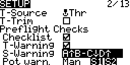
Preflight Checks (Warnings)
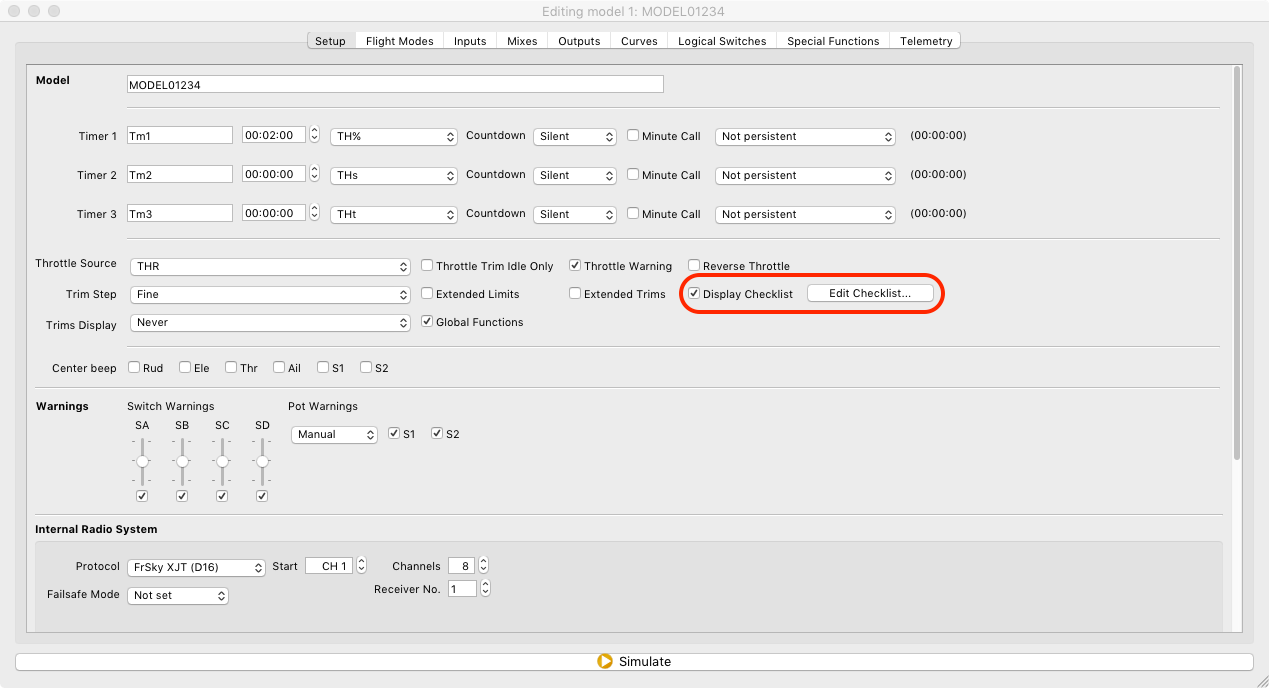
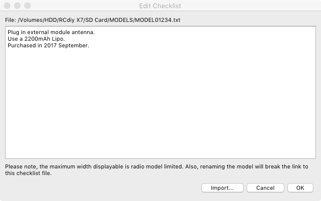
- Display Checklist – Displays the contents of a text file with the same name as the model and placed in the MODELS folder. This is also referred to as the model notes file.
Text beyond the screen width is not displayed.
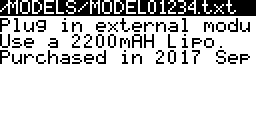
Taranis Q X7 Series
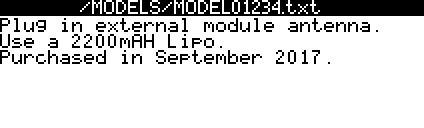
Taranis X9 Series
Create and edit this file using Companion.
- Throttle Warning – Enable or disable showing the throttle stick not idle warning when the transmitter is powered on and when a model is selected and loaded.
- Switch Warning – Displays a switch position warning when the transmitter is powered on and when the model is selected and loaded.
- Place all the switches in their desired positions.
- Scroll to the switch warning field.

- Long Press ENTER.
The switch positions get updated.
- Scroll to an individual switch.
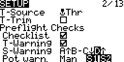
- Press ENTER to turn the warning off and on for that particular switch.
In this example the switch positions are
A (up/away) B (middle/centre) C (down/towards)
D is ignored
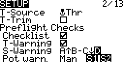
- Potentiometer Warnings – Knob, slider position warnings when the transmitter is powered on and when the model is selected and loaded.
- Off – Check not done.
- Manual – Select a knob (S1-S3) or slider (LS-RS) Long Press ENTER to save its current position.
- Auto – Stores knob or slider’s current position when the transmitter is powered of or a different model is selected and loaded.
Centre Beep
The transmitter beeps when the sticks, knobs and sliders enter or pass the center point.
- Scroll to the control.
- Press ENTER to turn on and off.
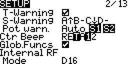
In this example the throttle stick and knob 1 are set to beep.
Global Functions
Use the global functions configured under the radio menus global functions screen. More…
Internal RF & Binding
The radio module inside the transmitter. For FrSKY transmitters this is an XJT module.
Mode
Transmission protocol of the internal RF module (OFF, D16, D8, LR12).
EU Firmware & Mode
The EU version of the firmware does not have the D8 option.
- The internal RF XJT module needs to be flashed with the EU version of the firmware. Download…
- The receivers need to be flashed with the EU version of the firmware. Download…
- OpenTX needs to be downloaded and flashed using the EU build option in Companion. More…
Channel Range
Choice of which of the radio’s internal channels are actually transmitted over the air. Choose any starting channel number and up to that number plus 15 for the second number.
- Typically CH1-8 and CH1-16.
- Maximum 16 channels.
- To transmit 32 channels set the internal module range CH1-16 and external module range CH17-32.
Latency (Delay)
The least delay is obtained by using a channel range of CH1-8.
The FrSKY protocol (PXX) and XJT RF module send 8 channels in each frame. Each frame is 9 milliseconds (ms).
When in D16 mode:
- Channel range set to CH1-8
- 1 PXX frames is used to send 8 channels.
- Updates are delayed by at least 9ms.
- Channel range set to CH1-16
- 2 PXX frames are used to send 16 channels, 8+8.
- The first frame has channels 1-8 and the second has channels 9-16.
- Updates are delayed by at least 18ms.
The SBUS protocol has 16 channels in each frame. Each frame is 9ms. Because the PXX protocol has 8 channels per frame 2 frames are used. Each SBUS frame has only 8 of its channels updated at a time so it takes 2 SBUS frames to have all 18 channels updated.
- Channel range set to CH1-8
- SBUS Frame 1 has CH1-8 updated, CH9-16 unchanged.
- It tales 1 frame to update all the channels.
- Updates are delayed by at least 9ms.
- Channel range set to CH1-16
- SBUS Frame 1 has CH1-8 updated, CH9-16 unchanged.
- SBUS Frame 2 has CH1-8 same as frame 1, CH9-16 updated.
- It takes 2 frames to update all the channels.
- Updates are delayed by at least 18ms.
Updates are delayed by at least the frame size delay. The total delay is:
- the time it takes the transmitter to read the inputs, process the inputs and pass them on to the RF module plus,
- the time it takes the RF modules to process the inputs into frames and transmit it plus,
- the time is takes the receiver to receive the frames, process the frames and output signals to servo pins or the SBUS.
Read this thread on the OpenTX GitHub issue tracker for more on observed latency.
Watch this YouTube play list by Drone Mesh in which observed latency results from testing various brands, protocols and channel ranges are presented.
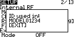
Receiver Number
A number used to bind a receiver using the D16 and LR12 protocols. The receiver binds to this number. Once bound a receiver will only respond to this number.
This number is a reference to an ID number that is unique. So two different receivers bound with the same receiver numbers will only respond to the transmitter to which they were bound.
The receiver number can be changed. By default this number is the same as the model slot number of the model select screen. If the model is moved or copied the receiver number stays the same.
When two or more models on the same transmitter have the same receiver number a warning is displayed.
Bind
This puts the transmitter into bind mode.
- Select and Press ENTER.
The cursor will blink and a sound is made every 2.5 seconds. - FrSKY Receivers
- Hold down the F/S button.
- Power On.
- Successful bind LEDs – Red blinking. Green on and not blinking.
- Release the F/S button and power off.
- Press EXIT or ENTER to leave bind mode.
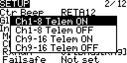
D16 Bind Options Menu
In RF D16 mode 16 channels are transmitted if the channel range is set to 1-16. The bind option determines if the servo pins are mapped to the first 8 channels or the second 8 channels. Further it also determines if telemetry from the receiver is turned on or off.
This is useful when using two receivers for redundancy or to connect more than 8 servos using two receivers.
While this is useful for two receivers this can be used with just one receiver.
- Requires latest transmitter XJT and receiver firmwares to have an effect. When used with with firmware prior to 170210 (2017 February 10) a regular bind takes place.
- The channel options are used to map the channels to the receiver servo pins.
- CH1-8 maps to servo pins 1-8 on receiver.
- CH9-16 maps to servo pins 1-8 on receiver; Channel 9 to pin 1.
- SBUS always has all 16 channels if the channel range is 1-16.
- The telemetry options turns telemetry on and off on receivers that support this feature.
- Works with X series of receivers using D16 mode; Instead of using a jumper to turn telemetry off.
- The XM receiver does not have telemetry but will bind and can be used.
- Has no effect on S series receivers but they will bind and can be used as stand alone receivers. When used as a redundancy receiver the SBUS it puts out will have the gyro feature results added to the signal. Turn the gyro off.
Single Receiver
- When using just one receiver use CH1-8 Telem ON or Off regardless of receiver type.
- Telemetry on and off will have an effect depending on receiver type being used.
Bind Two Receivers
It is the receiver that is bound to the transmitter. It is the receiver that determines which transmitter it will listen to.
To bind two receivers to be used at the same time use the following basic steps:
- Bind the first receiver as described in the bind section.
- Leave the receiver mode, channel range and number the same.
- Bind the second receiver as described in the bind section.
- For X series receivers turn telemetry off on one of the receivers using a jumper or use the bind options menu explained below.
- If two receivers are transmitting telemetry at the same time telemetry will not work. Only one receiver must be transmitting telemetry for telemetry to work.
Redundancy: Two Receivers
- One receiver needs to have an SBUS out and the other an SBUS in.
- One of the receivers needs to have its telemetry turned off.
- Only one of the receivers has servos connected to it.
- Connect a servo cable between one receiver’s SBUS out pins and the redundant capable receiver’s SBUS in pins or use a redundancy bus accessory. More…
More Than 8 Servos: Two Receivers
- One receiver needs to have an SBUS out and the other an SBUS in.
- One of the receivers needs to have its telemetry turned off.
- One receiver is bound with channels 1-8 and another with 9-16.
- Both receivers have servos connected to it.
Redundancy & More Than 8 Servos: Two Receivers
- One receiver needs to have an SBUS out and the other an SBUS in.
- One of the receivers needs to have its telemetry turned off.
- One receiver is bound with channels 1-8 and another with 9-16.
- Both receivers have servos connected to it.
- Connect a servo cable between one receiver’s SBUS out pins and the redundant capable receiver’s SBUS in pins or use a redundancy bus accessory. More…
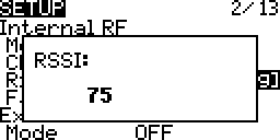
Range Check
This puts the transmitter into range check mode.
FrSKY transmitters transmit to 1/30th of their regular range when in range check mode.
- Select and Press ENTER.
The RSSI value is displayed and a sound is made every 5 seconds.
- Press EXIT or ENTER to leave range check mode.
Typical range check involves:
- Walking at least 30 paces away from the aircraft.
- Placing the transmitter into range check mode.
- Checking if the transmitter can still be controlled while the transmitter is in range check mode.
Failsafe Mode
Available on the transmitter when using D16 and LR12 protocols. The receiver will use this setting when the transmitter signal is not being received (signal loss).
- Hold – The receiver keeps channel values at their last received state from the transmitter.
- No pulses – No PWM pulses are output on the servo pins. The SBUS pin always has an output. When using SBUS use the hold, custom or receiver options.
- Receiver – Channel values are set by pressing the F/S button the receiver. Follow the instructions that come with the receiver.
- Custom – The receiver changes the channel values to the custom set values.
- Custom Set – Each channel can have its own setting. The options are a value, hold and no pulses.
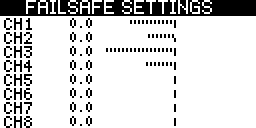
Taranis Q X7 Series
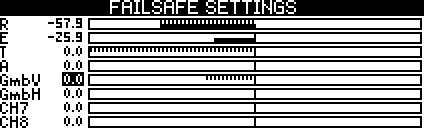
Taranis X9 Series
- Values
 The current values being transmitted on the channel.
 The current value being transmitted and the fail safe value set equal to it.
 The fail safe value.
 - Scroll to select a channel
- Long Press ENTER to change between a value, hold and none (no pulses)
- Press ENTER to set a value
The cursor will start to blink - Long Press ENTER to set that channel’s value equal to the current value being transmitted.
OR - Scroll to change the values
- Press ENTER to save the value
- Values
Failsafe Update
OpenTX sends the updated failsafe information to the FrSKY RF module. The FrSKY RF module sends the failsafe information to the receiver when it changes and periodically (every 9 seconds).
External RF (External Module Bay)
The radio transmitter module in the external module bay.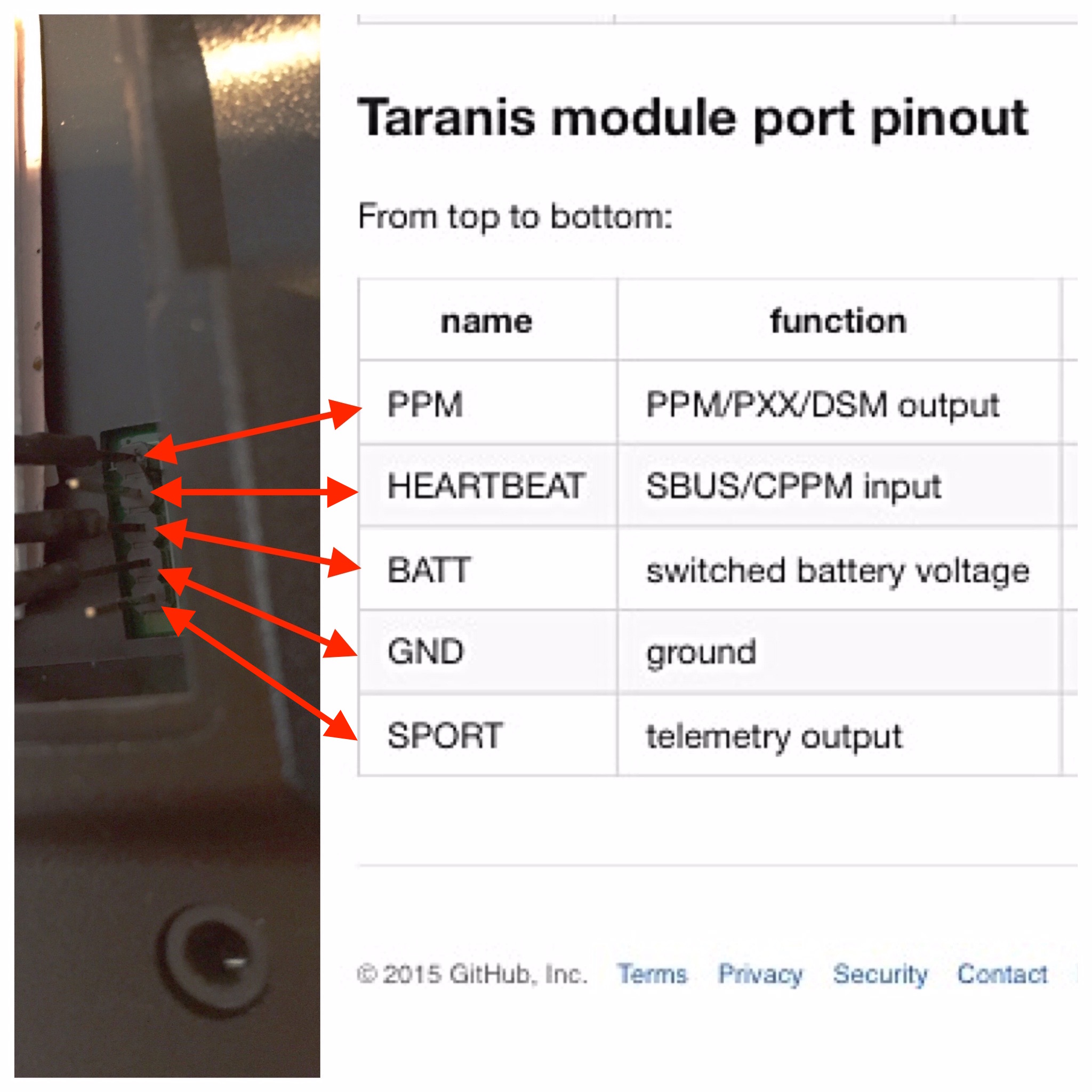
- Mode – When set to any value other than off the power to the external module bay is turned on. The voltage is the same voltage as the transmitter battery.
- PPM – Pulse position modulation, used by many generic JR compatible modules. Examples: OrangeRx Transmitter Modules , Spektrum DSM2 Module
- PPM Frame – Frame length, pulse length, and polarity of the PPM frame. The frame length is automatically adjusted to a safe value when the number of transmitted channels is changed.
- XJT – The FrSKY XJT Module.
- Same settings as the Internal RF.
- DSM2 – Spektrum DSM2/DSMX “non-hack/hack” module. Link 1 Link 2
- LP45, DSM2, DSMX
- MULT – DIY Multiprotocol TX Module.
- Available if selected in the build options. More…
- R9M – FrSKY R9M Long Range Module.
- SBUS – SBUS protocol out.
Examples: Trainer link, FrSKY SBUS To PWM decoder to attach servos.
- PPM – Pulse position modulation, used by many generic JR compatible modules. Examples: OrangeRx Transmitter Modules , Spektrum DSM2 Module
Trainer
Connect to another transmitter for training. Control of the aircraft is transferred back and forth by the instructor. More…
- Trainer mode
- Master – This transmitter is the instructor’s and is bound to the receiver. Signals are received from the student’s transmitter. This transmitter decides who has control of the aircraft.
- Slave – This transmitter is the student’s and is not bound to the receiver. Signals are sent to the instructor’s transmitter.
- Jack – Use the 3.5mm port and a cable to transmit and receive signals.
- Channel Range – 1-4 is a common settings but more channels may used.
- PPM Frame – Leave these settings at their defaults.
- SBUS – Use an SBUS module in the module bay.
- CPPM – Use a PPM module in the module bay.