Contents
Inputs ⇒ Mixer ⇒ Outputs
At this stage a channel receives the output from a mix and scales the percentage values to microsecond pulse widths.
-100% ⇒ 988μs
0% ⇒ 1500μs
100% ⇒ 2012μsThis assumes a 512μs minimum and maximum limit.
The mix percent value is processed by multiplying it with the travel limit in microseconds and then adding the PPM centre and subtrim values in microseconds. This is optionally used as an input to a curve to produce the final output.
(Mix% x travel limit μs) + PPM Centre μs + Subtrim μs ⇒ Curve
This final output will always be within the set minimum and maximum travel limits.
A channel without a mix centre’s it value to 0% ⇒ 1500μs.
Screen Layout
Taranis Q X7 Series

Taranis X9 Series
Top Row
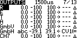
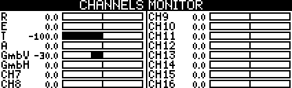
- Channel Monitor:
 The output from the selected line.
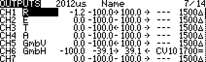
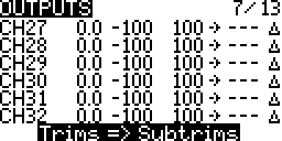
Columns
- Channel Name:
 The channel name will also be displayed on the mixer screen. On larger screens it also displays on the failsafe and channel monitor screens.
 - Channel Number:
 The channel number is displayed if no name is configured on smaller screens. Always displays on larger screens.
 - Subtrim: The channel offset from its configured centre value.
 Fixed
Fixed Global Variable
- Min/Lower & Max/Upper Limits:
 Servo travel limits in percent or microseconds.
Note: Instead of 100% you may see 512μs. This is done by selecting ppmus in Companion for the build options. More… - Current Output Position/Side:
 Left/Low
 Centre
 Right/High
- Servo Direction:
 Default
 Reverse
- Center Value Microseconds:
 The servo centre pulse width in microseconds.
 - Sub-trim Behaviour:
 Default/Asymmetrical – travel limit same on one side, shortened on the other side, preserve curve. There is a region where when the servo does not move when the stick moves.
 Symmetrical – travel limits stay the same, curve changes. The servo always moves when the stick moves.
Editing
General editing instructions are covered on the Screen Navigation page under editing.
Context Menus
Taranis Q X7 Series
Taranis X9 Series
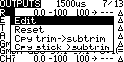
- Edit: On the Taranis Q X7 to edit the settings.
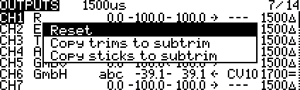
- Copy trims to subtrims: The trim offset from the sticks is coped to the subtrim.
- If stick is 0%, trim is 20%, centre is 0%, subtrim 0%, Output 20%
Copy trims to subtrims
Now stick is 0%, trim is 20% of 80%, centre is 0%, subtrim 20%, Output 36%
- If stick is 0%, trim is 20%, centre is 0%, subtrim 0%, Output 20%
- Copy sticks to subtrim: The stick position % gets copied to the subtrim.
- If stick is 20%, trim is 0%, centre is 0%, subtrim 0%, Output 20%
Copy trims to subtrims
Now stick is 20% of 80%, trim is 0%, centre is 0%, subtrim 20%, Output 36%
- If stick is 20%, trim is 0%, centre is 0%, subtrim 0%, Output 20%
Settings
Taranis Q X7 Series
Taranis X9 Series
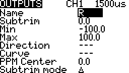
Name
The channel name will be displayed on the outputs screen and also on the mixer screen. On larger screens it also displays on the failsafe and channel monitor screens.
CH name on mixer screen – Taranis Q X7 Series
CH name on mixer screen – Taranis X9 Series
CH names on channel monitor screen – Taranis X9 Series
Subtrim
The subtrim setting is an offset similar to trim. When the source is centred the servo will be at the PPM centre value plus this subtrim value.
Use subtrim to:
- Center or align the control surfaces on the bench.
- Give back travel range to the trims. Usual trim range is 25% of the stick range.
- Preserve trim settings between model changes. This is a way to ensure that the model always has the correct trim when loaded.
Min Limit
The lower limit for the servo travel with respect to the PPM centre value.
Set the channel source/input to minimum, -100%, and then watch the servo. Adjust this limit till the servo no longer gets stuck or the maximum desired travel is reached.
Max Limit
The upper limit for the servo travel with respect to the PPM centre value.
Set the channel source/input to maximum,100%, and then watch the servo. Adjust this limit till the servo no longer gets stuck or the maximum desired travel is reached.
Direction
The direction of the servo is reversed if INV is selected.
Curve
A custom curve or an inverse of a custom curve may be selected.
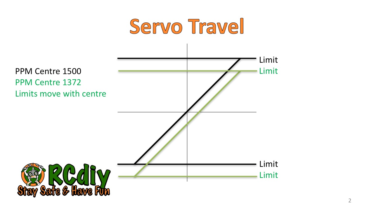
PPM Centre
Similar to subtrim with the difference being that the minimum and maximum limits change when the centre changes. Limits are with respect to the centre.
Trims To Subtrims
The trim offset is coped to the sub trim. The trim gets reset to zero. Read the explanation of subtrim above for more information.
Select this row and Press ENTER.
Servo Movement
PPM Centre & Limits
Servos are made to centre their movement at a particular pulse width setting. Most RC servos centre at 1500 microseconds.
For simplicity, here we will transfer the pulse width modulation (PWM) explanation to apply to pulse position modulation (PPM). More…
The limits are the maximum amount of movement either side of the servo’s centre position. In OpenTX, with default settings, the maximum limit of 100% equates to 512 microseconds.
-100% ⇒ 988μs
0% ⇒ 1500μs
100% ⇒ 2012μs
When the centre value is changed the limits change.
Subtrim Modes
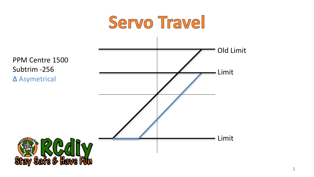
Default Asymmetrical
In the default asymmetrical subtrim the limit on one side gets shortened by the subtrim amount. While the limit on the other side stays the same. The curve as configured in the inputs and mix stages is preserved.
If a stick is being moved, on one side of centre, the servo stops moving before the stick stops moving.
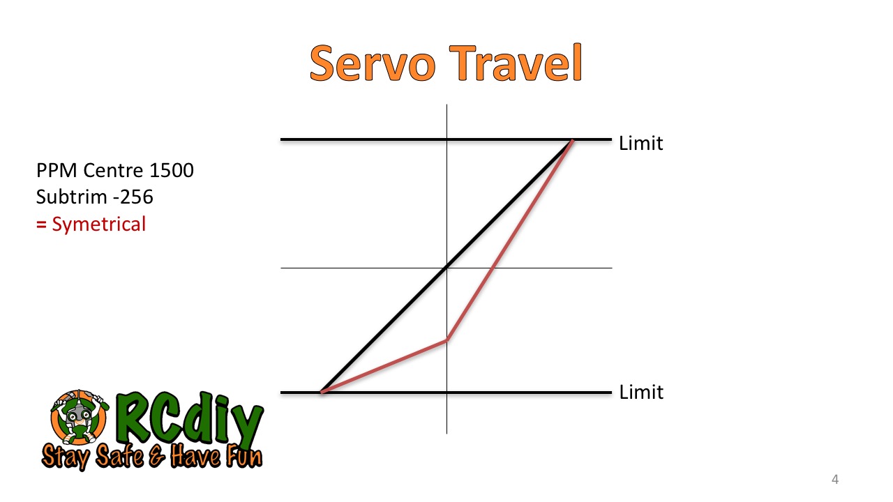
Symmetrical
In the symmetrical subtrim the limit both sides stay the same. The servo travels to both the limits as it did before the subtrim was set to a non-zero value. The curve as configured in the inputs and mix stages is now modified to scale with the preserved limits but changed centre.
If a stick is being moved the stick and servo stop moving together.