
OpenTX
Contents
The head speed of a helicopter is the revolutions per minute of the main rotor.
The OpenTX RPM sensor has two fields that will help calculate the head speed:
- Blades
Set Blades = Number of Main Gear Teeth
Blades acts as a divider. The sensor data received is divided by the blades value. - Multiplier
Set Multiplier = Number of Pinion Gear Teeth
The sensor data received is multiplied by this value.
Displays
- Head Speed
Sensor
- RPM Sensor
Theory
Example
- Motor Pole Pairs = 7
- Main Gear Teeth = 162
- Pinion Gear Teeth = 14
Information Flow
ESC Motor Pulses > RPM Sensor Hardware > OpenTX RPM Telemetry > Head Speed
- ESC Motor Pulses
- The ESC produces Motor Pulses
- FrSKY RPM Sensor Data
- The Motor Pulses are Detected by the RPM Sensor
- The RPM Sensor outputs the RPM calculated based on the pulses and the number of motor magnetic pole pairs
- OpenTX RPM Telemetry
- The Sensor Data is read by OpenTX
- OpenTX either displays the RPM as provided by the Sensor or corrects the Sensor Data
- Head Speed Calculation
- The OpenTX RPM Telemetry is used to calculate the main rotor’s Head Speed
- The Head Speed is calculated based on RPM, Number of Main Gear Teeth and Number of Pinion Gear Teeth
Configuration Choices
There are a number of ways to configure the system to get the RPM and Head Speed.
- RPM – To get the correct RPM there are two ways to configure the system
- Set the number of magnetic pole pairs on the RPM Sensor Hardware. In this case the RPM is correct and no corrections are required in the OpenTX RPM Telemetry.
- Leave the number of magnetic pole pairs on the RPM Sensor Hardware set to 1. In this case the RPM is corrected in the OpenTX RPM Telemetry settings.
- Head Speed – To calculate and display the head speed there are two choices
- Use OpenTX Telemetry to calculate and display the Head Speed based on the RPM.
- Use the Head Speed Lua Script to calculate and display the Head Speed based on RPM.
RPM Sensor Hardware
The FrSKY RPM Sensor senses electrical pulses. These pulses are proportional to the number of motor magnet (pole) pairs.
Example RPM Sensor Hardware Configuration Options:
- The FrSKY RPM sensor can be configured with the number or pole pairs, say 7, so that the RPM value that is reported by the sensor is correct.
- If the RPM sensor is configured with pole pairs as 1 but the actual pole pairs is say 7 the the RPM value reported by the sensor will be 7 times higher. In this case we account for this by setting blades to 7 so that sensor data is divided by 7.
OpenTX RPM Telemetry
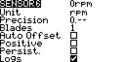
The OpenTX RPM Telemetry settings have two fields to configure:
- Blades – this acts as a divider on the RPM hardware sensor data
- Multiplier – this acts as a multiplier on the RPM hardware sensor data
- Both have a range of acceptable value settings from 1 to 30,000
- RPM = RPM Sensor Hardware Data x Multiplier/Blades
Example OpenTX RPM Sensor Settings Options To Get RPM:
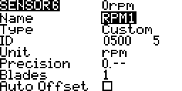
- RPM sensor values are correct, magnet pole pairs set to 7
- Set Blades = 1
- Set Multiplier = 1
- Result OpenTX RPM = RPM Sensor Data
- RPM sensor values are incorrect, magnet pole pairs set to 1
- Set Blades = 7
- Set Multiplier = 1
- Result OpenTX RPM = RPM Sensor Data/7
Head Speed Calculations
The head speed is calculated as follows:
- Gear Ratio = Main Gear/Pinion Gear Number Of Teeth
- Head Speed = RPM/Gear Ratio
Head Speed = RPM x Pinion/Main
Example OpenTX RPM Sensor Settings Options To Get Head Speed:
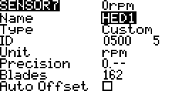
- RPM sensor values are correct, magnet pole pairs set to 7
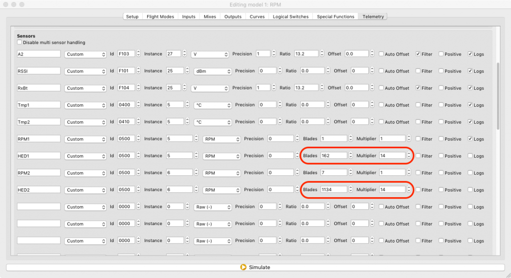
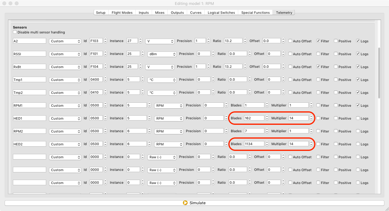
- Set Blades = Main Gear Teeth = 162
- Set Multiplier = Pinion Gear Teeth = 14
- Result Head Speed = RPM Sensor Data x Pinion/Main
Result Head Speed = RPM Sensor Data x 14/162
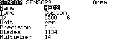
- RPM sensor values are incorrect, magnet pole pairs set to 1
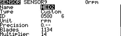
- Set Blades = 7 x Main Gear Teeth = 7 x 162 = 1,134
- Set Multiplier = 1 x Pinion Gear Teeth = 1 x 14 = 14
- Result Head Speed = Sensor Data x Pinion/(Main x 7)
Result Head Speed = RPM Sensor Data x 14/1134
Setup
- To set up the RPM sensor hardware and OpenTX follow these instructions
- Make a copy of the RPM sensor
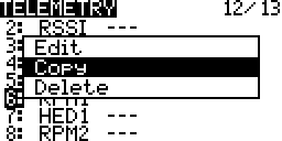
- Rename the Copy
- Depending on how the RPM Hardware Sensor is configured set
- Blades = Main Gear Teeth E.g. 162
Multiplier = Pinion Gear Teeth E.g. 14

- Blades = Magnetic Pole Pairs x Main Gear Teeth E.g 7 x 162 = 1,134
Multiplier = Pinion Gear Teeth E.g. 14
- Blades = Main Gear Teeth E.g. 162
- As of August 2017 the Taranis Q X7 firmware is missing the Multiplier field
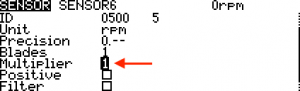
- To configure the Multiplier on the Taranis Q X7 use Companion


Companion File
- hdspd-x7.otx.zip
- The file has four sensors set up with the values from the examples on this page.
- RPM1 & HED1 – Use these if the RPM Sensor Hardware has the number of magnetic poles configured and the RPM output is correct.
- RPM2 & HED2 – Use these if the RPM Sensor has the number of magnetic poles configured as 1 so the RPM output has to be corrected.
- Open the file using Companion and run the simulator.
- Open the simulator
- View > Telemetry Simulator
- To view the telemetry from the main view Long Press Page
- Adjust the RPM on the Telemetry Simulator as shown in the pictures


Comments, Questions & Help
- Flite Test Forum Head Speed
Credits
- Dean Church