
Contents
Screen Layout
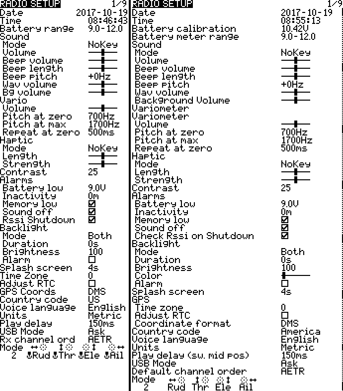
Taranis Q X7 series on the left & Taranis X9 series on the right
Editing
General editing instructions are covered on the Screen Navigation page under editing.
Settings
Date
The date in YYYY-MM-DD format. This is used in log files.
Time
The time in 24 hour format. This is used in log files.
Battery Calibration
Adjust this value to match the transmitter battery voltage measured using a voltmeter.
Only available on the Taranis X9 Series. The X7 has the same configuration on the ANALOGS screen. More…
Battery Range
The battery range is used to scale the battery meter gauge.
Here are some suggested ranges based on tests. More…
- NiMh 6 cells 800 mAh – 7 to 8 volts
About 1 hour remaining at 7 volts, 4 hours at 8 volts. - NiMh 6 cells 2400 mAh – 7 to 8 volts
About 2 hour remaining at 7 volts 12.5 hours at 8 volts. - Lipo 3 cell 800 mAh – 11 to 12 volts
About 1 hour remaining at 11 volts, 6 hours at 12 volts.
Sound
Sounds are made in two ways. The first is transmitter generated beeps and tones and the second is by playing wave files on the optional SD Card. More…
Mode
Configure if sounds are made when the buttons are pressed.
- All: Beeps when the buttons are pressed and when when there are alerts or warnings.
- No Key: No sounds when buttons are pressed or scroll wheel is turned but does when there are alerts or warnings.
- Alarm: Sounds only when there are warnings such as switch and throttle position warnings but no sounds on trim adjustment.
- Quiet: No sounds. More…
Volume
The main volume that overrides all other volumes.
Beep Volume
The volume for transmitter generated beeps and tones.
Beep Length
The length of the transmitter generated beeps and tones.
Beep Pitch
The pitch/frequency of the transmitter generated beeps and tones. The frequency can be changed up to +300 Hz from its default value
Wave Volume
The volume for wave file playback. More…
Bg Volume
The volume for background wave file playback.
Variometer
The variometer is used by gliders to track sinks and climbs.
Volume
The volume for transmitter generated sink and rise tones.
Pitch At Zero
The pitch/frequency at the start of the sink or rise range configured on the model’s TELEMETRY screen (more…). The frequency range is from 300 to 1,100 Hz.
Pitch At Max
The pitch/frequency at the end of the sink or rise range configured on the model’s TELEMETRY screen(more…). The frequency range is from 500 to 2,100 Hz. The lower number is auto adjusted in the pitch at zero increases to within 200 Hz. For example if the pitch at zero is 1,000 Hz then the pitch at max forced to be at least 1,200 Hz.
Repeat At Zero
The gap in milliseconds before the tone repeats. The range of value is from 200 to 1,000 milliseconds. This is equivalent to 5 beeps per second to 1 beep per second.
Haptic
The transmitter vibrates. This is available in the Taranis X7 series X9D Plus series and the X9E.
Mode
Configure if vibrations are made when the buttons are pressed.
- All: Vibrates when the buttons are pressed and when when there are alerts or warnings.
- No Key: No vibration when buttons are pressed and scroll wheel is turned but does when there are alerts or warnings.
- Alarm: Vibrations when there are warnings such as switch and throttle position warnings but no vibrations on trim adjustment.
- Quiet: No vibrations.
Length
A slider that adjusts the length of the vibrations.
Strength
A slider that adjusts the strength of the vibrations.
Contrast
The LCD screen contrast settings.
Alarms
Battery Low
The transmitter battery low level at which a sound or announcement is made.
Here are some suggested ranges based on tests. More…
- NiMh 6 cells 800 mAh – 7 volts
About 1 hour remaining at 7 volts. - NiMh 6 cells 2400 mAh – 7 volts.
About 2 hour remaining at 7 volts. - Lipo 3 cell 800 mAh – 11 volts
About 1 hour remaining at 11 volts.
Inactivity Alarm
The inactivity time in minutes after which a sound or announcement is made as a reminder that the transmitter is still on. Inactivity is tracked based on moving a stick, switch, knob or pressing a navigation button.
Memory Low
The run time (RAM) memory low warning.
Sound Off
An alarms disabled warning is displayed when the transmitter is turned on if the sound mode is set to quiet. More…

RSSI Shutdown
A warning is announced and displayed when the radio is being shutdown with a receiver on and connected. If the shutdown continues a confirm shutdown screen is displayed with the option to press ENTER to shutdown or press EXIT to not shutdown.
Backlight
The LCD has a backlight to help read the display in low light conditions.
Mode
- Off – Always off.
- Keys – Turns on when navigation buttons are used.
- Ctrl – Turns on when sticks, switches and knobs are used.
- Both – Turns on when navigation buttons, sticks, switches and knobs are used.
- ON – Always on.
Duration
The length in seconds that the light is on. At zero seconds the light stays off all the time except when the mode is set to on. The values increment in 5 second jumps up to a maximum of 600 seconds.
Brightness
The backlight intensity from 0% (off) to 100% (maximum) brightness.
Alarm
The lcd backlight light turns on when there are alarms.
Splash Screen
The duration in seconds the start up screen is shown for. Setting this to zero disables the splash screen.

Taranis Q X7 Series Splash Screen
GPS
The FrSKY GPS sensor’s values are adjusted or formatted based on these settings.
Time Zone
The time zone to be used with a GPS. This is a UTC value from -12 to 12 hours. Only integers are possible. More…
Adjust RTC
Adjust the real time clock, the transmitter’s clock, to match the time determined by a GPS sensor.
Coordinate Format
The GPS coordinate format for the display. The logs are always in decimal format.
- DMS:

- NEMA:

Country Code
The radio is set to be complaint with regulations related to radio wave transmission. This information is sent to internal XJT module which takes care of the regulatory requirements.
- America
- Japan
- Europe
Note: 2017 October 7 – This may be used in the future by internal GPS modules for transmitters that have them.
Voice Language
The language of the announcements when an SD Card with a voice pack is present. More…
Units
The default telemetry units. For example a temperature sensor will default to Celsius instead of Fahrenheit if this is set to metric.
- Metric
- Imperial
Play Delay
The minimum time in milliseconds a switch must be in the middle position before a special function will get activated. The range is from 0 milliseconds to 1,000 milliseconds. For example if a three position switch is linked to play three announcements then moving from all the way up to all the way down will skip the middle announcement if the play delay is set large enough.
FAI Mode
Enable Federation Aeronautique Internationale (FAI) mode. It disables all telemetry displays, other than RSSI and voltage, to comply with FAI regulations for contests, championships, and record setting activities. Once engaged, this option remains in effect until the firmware is re-flashed.
This setting is present if selected as a build option when the firmware is downloaded. More…
USB Mode
The behaviour when a USB cable is connected a computer and the transmitter while both are on.
- Ask – A context menu is displayed.
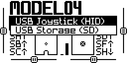
- Joystick: The transmitter can be used a USB joystick.
- Storage: Two drives get mounted. The Taranis drive and the SD Card drive (if and sd card is present).
Rx Channel Order
The default channel order for new models and TRAINER screen display. The mixes for new models get set up to map the sticks to channels based on this order. This order can be changed on the MIXER screen for existing models. Changing this channel order here will not affect existing models.
There are 24 possible channel order configurations. One suggested channel order to default to for new models is:
- AETR – FrSKY Receivers with a gyro for flight stabilization.
A – Aileron, E – Elevator, T – Throttle, R – Rudder
Mode (Transmitter Sticks)
The transmitter stick mode is the arrangement and use of the control sticks.
It is essential that this matches how the sticks are configured and used.
Mode 1 and 2 are the most common configurations used.
| Mode | Left Horizontal | Left Vertical | Right Vertical | Right Horizontal |
|---|---|---|---|---|
| 1 | Rudder | Elevator | Throttle | Aileron |
| 2 | Rudder | Throttle | Elevator | Aileron |
| 3 | Aileron | Elevator | Throttle | Rudder |
| 4 | Aileron | Throttle | Elevator | Rudder |