
Contents
Logic switches are similar to two position transmitter switches. They have two states, false (-100%) and true (100%). A basic logic switch consists of a conditional function, two values and a result.
Value 1 Condition Value 2 ⇒ Result
5 = 5 ⇒ true
4 > 5 ⇒ false
Logic conditions and results are false and true. They are combined using the basic operations AND, OR, XOR (exclusive OR) and NOT (!).
true AND false ⇒ false
true AND true ⇒ true
true OR false ⇒ true
true OR true ⇒ true
true XOR false ⇒ true
true XOR true ⇒ false
NOT true ⇒ false
!true ⇒ false
A Logical switch’s result may also be controlled by another switch; the AND switch. When this switch is false the logical switch is always false. When this switch is true or not configured the logical switch is false or true depending on the condition and values.
( Value 1 Condition Value 2 ⇒ Result ) AND switch ⇒ Result
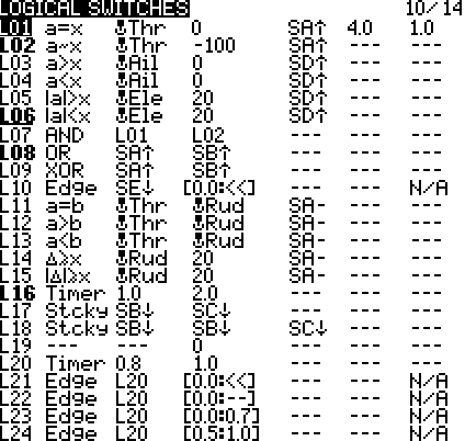
Screen Layout
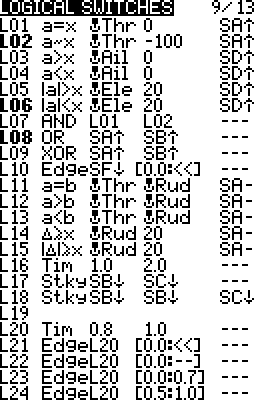
Taranis Q X7 Series
Columns
- Name:
 The name that appears in the list of sources. When bold the switch is true.
 - Function (condition):
 The condition/test to apply to the values.
 - Value 1:
 The value to the left of the function/condition.
 - Value 2:
 The value to the right of the function/condition.
 - AND Switch:
 Used to turn off (false) or on (true) the entire logical switch. Usually a transmitter or another logical switch but can be any source.
 - Duration:
 The length of time in seconds the logical switch may be forced to stay true. It is forced to false at the end of the duration regardless of the condition’s result.
 - Delay:
 The time in seconds after which the logical switch’s current condition may change to true of false. If the condition goes true and then false within the delay then the logical switch stays false.
Editing
General editing instructions are covered on the Screen Navigation page under editing.
Edit A Logical Switch
Taranis Q X7 Series
- Long Press Enter
Select EDIT

- Press ENTER
Taranis X9 Series
- Press Enter
Copy & Paste
- Long Press Enter
Select Copy
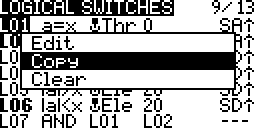
- Press ENTER
- Scroll to the desired logical switch row
- Press ENTER
Select Paste
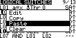
- Press ENTER
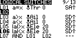
Clear
- Press Enter
Select Clear
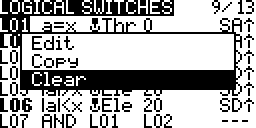
- Press ENTER
Settings
The settings are context sensitive depending on the function chosen.
- a, b represent sources that are variable against which to compare.
- x represents a configured constant against which to compare.
- =, ~, <, >, AND, OR, XOR, ≤, ≥ represent the condition to test for.
Telemetry Sources
Telemetry sources are treated as values or true and false depending on the logical function being used. In functions where two values are being compared then the value of the telemetry source is used. In operator functions such as AND, OR, XOR the telemetry value is true when data is being produced.
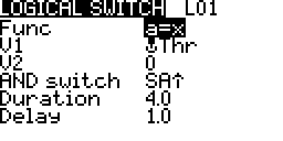
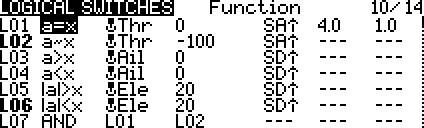
a, x Functions – Source (a) vs. Constant (x)
a=x Equal
![]()
True for four seconds, after a one second delay, if the value of the throttle stick stays equal to zero for at least one second.
If within the one second delay the condition goes false then the logical switch stays false.
This has the effect of staying false unless the throttle stick is exactly at the centre for at least one second.
a~x Almost Equal
![]()
True while the throttle stick is almost equal to -100% and switch A is up.
Almsot equal is when the values are within -1.6% to +1.6% of each other.
This has the effect of staying false when the throttle is not all the way down.
From the source code More 1, More 2.
result = (abs(x-y) < (1024 / STICK_TOLERANCE));
#if defined (PCB9XR) || defined (PCB9XR128)
#define STICK_TOLERANCE 16
#else
#define STICK_TOLERANCE 64
#endif
a>x Greater Than
![]()
True while the aileron stick is greater than 0% and switch D is up.
This has the effect of staying false when the aileron stick is centred of is left on centre.
a<x Less Than
![]()
True while the aileron stick is less than 0% and switch D is up.
This has the effect of staying false when the aileron stick is centred of is right on centre.
|a|>x Absolute Value Greater Than
![]()
True while the absolute value of the elevator stick is above 20% and switch D is up stay true.
This has the effect of staying false as long as the elevator stays within 20% of the centre.
|a|<x Absolute Value Less Than
![]()
True while the absolute value of the elevator stick is below 20% and switch D is up.
This has the effect of staying true as long as the elevator stays within 20% of the centre.
Operator Functions – Switch vs. Switch
AND – Both Values True
![]()
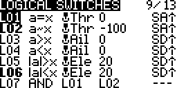
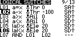
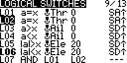
True while logical switch one and logical switch two are both true.
Assuming that L01 and L02 are configured as shown below.
![]()
![]()
This is only possible if the throttle is exactly centred for between 1 to 4 seconds and then moved all the way down. At the end of 5 seconds the switch if forced false; 1 second delay plus 4 second duration.
OR – Either Value True
![]()
True while switch A is up or switch B is up stay.
XOR – Only One Value True
![]()
True while only one of switch A is up or switch B is up.
If both both transmitter switch A and transmitter switch B are up then stay false.
a, b Functions – Source (a) vs. Source (b)
a=b Equal
![]()
True while value of the throttle stick is equal to rudder stick and switch A is centred.
a>b Greater Than
![]()
True while value of the throttle stick is greater than the rudder stick and switch A is centred.
a<b Less Than
![]()
True while value of the throttle stick is greater than the rudder stick and switch A is centred.
Δ≥x Increment Interval Greater Than Equal To
![]()
This is a momentary condition (about 30 milliseconds).
True every time the value of the rudder stick increases by 20.
This could be used with an altitude sensor and every time the altitude increases by 10 meters have the logical switch stay true.
Tip: Set the duration to 0.5 second or more if are having trouble getting it to work or observe its changing state.
|Δ|≥x Absolute Increment Interval Greater Than Equal To
![]()
This is a momentary condition (about 30 milliseconds).
True every time the value of the rudder stick increases or decreases by 20.
This could be used with an altitude sensor and every time the altitude increases or decreases by 10 meters have the logical switch stay true.
Tip: Set the duration to 0.5 second or more if are having trouble getting it to work or observe its changing state.
Special Functions
Timer
A timer logical switch periodically changes its state between false and true.
Value 1 is the true duration.
Value 2 is the false duration.
![]()
True for one second. False for two seconds. Repeats.
At the start of every three seconds stay true for one second.
Value 1 and value 2 get added together to determine the repeat cycle in seconds.
Sticky
A sticky logical switch holds its true value, sticks true, till it is forced false.
Value 1 is the first switch. This sets the sticky true when it changes from false to true.
Value 2 is the second switch. This sets the sticky false when it changes from false to true.
When the sticky is false only value 1 is watched for a change and is evaluated. Value 2 is ignored.
When the sticky is true only value 2 is watched for a change and evaluated. Value 1 is ignored.
When the sticky changes and the watched value is already true it is ignored. That value has to change back to false and then true again to cause the sticky to change.
![]()
When transmitter switch B change to true (down) the sticky becomes true and stays true regardless of how switch B changes state.
true STICKY false ⇒ true
Now only switch C is evaluated but only when it changes.
When switch C changes to true (down) the sticky becomes false and stays false regardless of how switch C changes state.
true STICKY true ⇒ false
Now only switch B is evaluated but only when it changes.
false STICKY true ⇒ false
true STICKY true ⇒ true
Now only switch C is evaluated but only when it changes.
true STICKY false ⇒ true
true STICKY true ⇒ false
This acts like a see saw.


When a weight is dropped on the left it tilts left. Now if the weights stays or falls off it stays down on the left.
When a weight is dropped on the right it tilts right. Now if the weight stays or falls off it stays down on the right.
This analogy is not completely appropriate but it does help to get started understanding how the sticky works.
Edge
An edge switch is a momentary switch (about 30 milliseconds) that changes its state depending on the direction of change of its one monitored switch.
Value 1 is the monitored switch.
Value 2 becomes two parts; Minimum and Maximum monitored switch duration.
Minimum is the minimum duration value 1 must stay true to trigger the edge switch.
Maximum is the maximum duration value 1 must stay true to trigger the edge switch.
![]()
Leading Edge – True for a moment when the monitored switch goes from false to true.
![]()
Trailing Edge – True for a moment when the monitored switch goes from true to false.
![]()
Trailing Edge Monitoring Duration – True for a moment if the switch stays true for no more than 0.7 seconds.
![]()
Trailing Edge Monitoring Duration – True for a moment if the switch stays true for at least 0.5 seconds and no more than one second.
AND Switch Values
- Transmitter or logical switch – Active when the set condition matches.
- One – Active momentarily once when the model is loaded.
- ON – Always active.
- Trim Movement – Active when the selected stick trim is moved in the selected direction. The choices are Rudder Trim Left , Rudder Trim Right, Elevator Trim Up, Elevator Trim Down, Throttle Trim Up, Throttle Trim Down, Aileron Trim Left, and Aileron Trim Right.
- Flight Modes – Active when the selected flight mode is active.
- Telemetry Sources – Active when telemetry data is being produced.