
Contents
Inputs ⇒ Mixer ⇒ Outputs
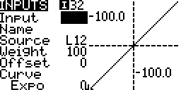
This stage receives inputs from sources (explained below) and produces outputs to be used in the mixer stage (screen). The source is processed by multiplying its value by a weighting %, adding an offset and applying a curve. Values are in the range -100% to 100%.
(Source x Weight) + Offset ⇒ Curve
Raw sources such as sticks and switches are processed and their outputs may be different compared to the raw values. For example when rates are set on the sticks its raw value may be 100% but its processed output maybe 75%. So a sticks full travel may result is a lower servo travel. A complete list of sources is provided below.
Most pilots use this screen to only configure the four sticks, Throttle, Rudder, Elevator and Aileron. Switches, sliders and knobs are usually added on the MIXER screen.
Screen Layout

Taranis Q X7 Series

Taranis X9D Series
Top Row
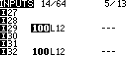
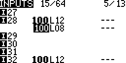
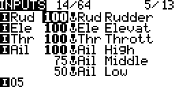
- Lines Used/Capacity:
 The number of input lines configured out of a possible total.
 - Line Monitor:
 The output from the selected line.
Columns
- Input Name:
 How the processed source will appear in source lists.
 - Weight:
 The weight % applied to the source.
 - Source:
 Unprocessed/raw source. How the source appears in source lists.
 - Switch:
 No switch configured. Processing always active.
 Switch configured. Processing active when switch condition is true (SB up/away).
- Line Name:
 The name of that processing line.
Processing
Switches
Each input may have a selectable activation switch. When no switch is configured the processing line is always active subject to the flight mode active condition. There are up to 32 possible inputs and 64 possible input lines can be configured; More on this below.
Priority
When two or more processing lines for the same source are active the first/top line is used.
Hold
When a source has no processing lines active that last value is held constant.
Editing
General editing instructions are covered on the Screen Navigation page under editing.
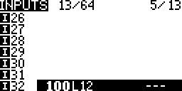
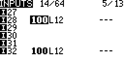
Empty Input Line (Create An Input)

- Press ENTER
The settings screen is displayed and a processing line gets created.
- Press EXIT
Occupied Input Line
Copy
- Press ENTER
The whole line gets selected.
- Scroll to copy the line.
- Press ENTER to place a copy of the line.
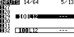
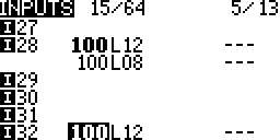
Move
- Press ENTER
The whole line gets selected

- Press Enter again
The selected line now has a dotted border.
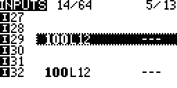
- Scroll to move the line.

- Press ENTER to place the moved line.
Insert (Multiple Lines Per Input)
- Long Press ENTER
A context menu is displayed
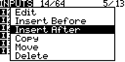
- Select one of the insert options
- Press ENTER
The settings screen is displayed and a processing line gets created.
- Press EXIT
Delete
- Select a line.
- Long Press ENTER
A context menu is displayed.
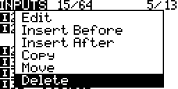
- Select Delete
- Press ENTER

Edit
- Select an input line
- Long Press ENTER
A context menu is displayed
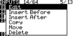
- Select Edit
- Press ENTER
The settings screen is displayed.
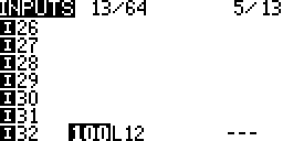
Number of Inputs & Input Lines
Up to 32 possible inputs and 64 possible input lines can be configured. Each input may have one or more lines.
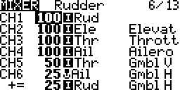
CH6 has two mix lines. On this screen 6 mixes and 7 mix lines are seen.
- If 32 inputs have 1 input line the the total number of possible inputs stays at 32 and 32 out of 64 mix inputs have been used.
- If 32 inputs have 2 input lines the the total number of inputs stays at 32 and 64 out of 64 input lines have been used. Now if one on the inputs needs a third input line then another input will need to have it’s input line removed.
- 32 inputs can not have 3 input lines each. This would be attempting 96 input lines which exceeds the 64 input line maximum.
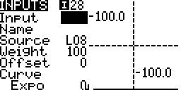
Settings
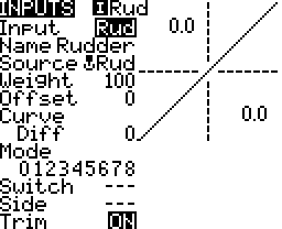
Taranis Q X7 Series
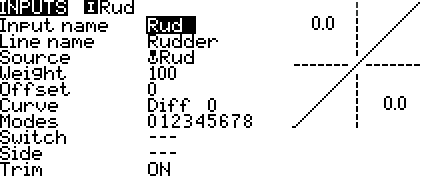
Taranis X9D Series
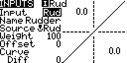
The Graph
The horizontal axis and lower left number represent the source value.
The vertical axis and upper right number represent the output value from this input line.
Input Name
The name that displays next to the inputs symbol and in source lists![]()
Line Name
The name that displays on the inputs list screen.
Source

- Sticks – Aileron, Elevator, Rudder and Throttle.
- Pots – Knobs and sliders.
- MAX – A fixed 100% value.
- Cyclic – CYC1 to CYC3 from the Heli Setup screen if present
- Trims – Aileron, elevator, rudder and throttle stick trims.
- Switches – Transmitter switches SA to Sh if present.
- Trainer – Trainer channels
- Channels – The outputs that get transmitted
- Telemetry – Data from sensors
While editing the source:
- Long pressing ENTER brings up a context menu to jump to a grouping in the list of sources.
- Move a source, Sticks, Pots, Trims, Switches, to select it.
Weight
Percentage value of stick travel to use.
Long Press ENTER changes from the static value to a global variable’s value.

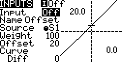
Offset
The value by which the source is added to or subtracted from.
When viewing the graph the output line/curve is moved up or down the vertical (output) axis.
Curve
The source (plus offset) is changed by applying a mathematical function to it after the weight and offset have been applied.
((Source x Weight) + Offset) x Curve
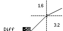
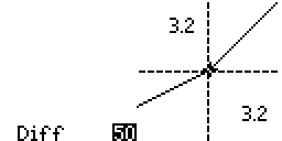
Diff (Linear)
- When the diff value is zero it is the the default linear curve. The output if equal to the input.

Diff without offset
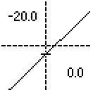
Diff with offset
- If the diff value is not zero then the output is linear but the slope is different on either side of the centre, zero value.
Expo (Exponential)
The output changes less near the input’s centre compared to the inputs travel ends.
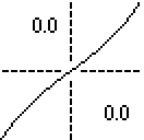
Expo without offset
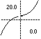
Expo with offset
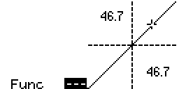
Func (Function)
- – – – When the function is not not defined the output is equal to the input.
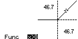
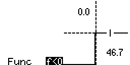
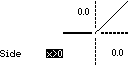
- x>0 The output is equal to the input when the input is greater than zero, else the output is zero.
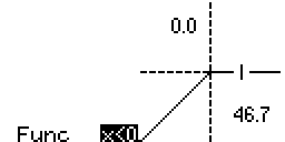
- x<0 The output is equal to the input when the input is less than zero, else the output is zero.
- |X| The output is equal to the input in magnitude but is always positive.

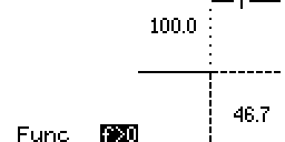
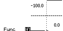
- f>0 The output is 100% when the input is greater than zero, else it is 0%
- f<0 The output is -100% when the input is less than zero, else it is 0%
- |f| The output is 100% when the input is greater than zero, else it is -100%

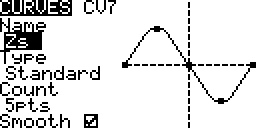
Cstm (Custom)
Use a custom curve configured on the curves screen. More…
- Select the custom curve and keep the cursor flashing

- Long Press ENTER to edit that curve
Modes
The flight modes the input line is active in. When none are selected it is active is all flight modes. The modes, switch and side conditions are combined to determine the final active status.
Switch
The switch that activates the input line. If none are defined then it is always active. The modes, switch and side conditions are combined to determine the final active status.
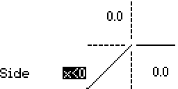
Side
The side of centre of the input that activates the input line. The modes, switch and side conditions are combined to determine the final active status.
Trim
Turn on or off the inclusion of trim if when it exists for an input or select another sticks trim (Rudder, Elevator, Throttle, Aileron trim).